55
Chapter 2: Installation
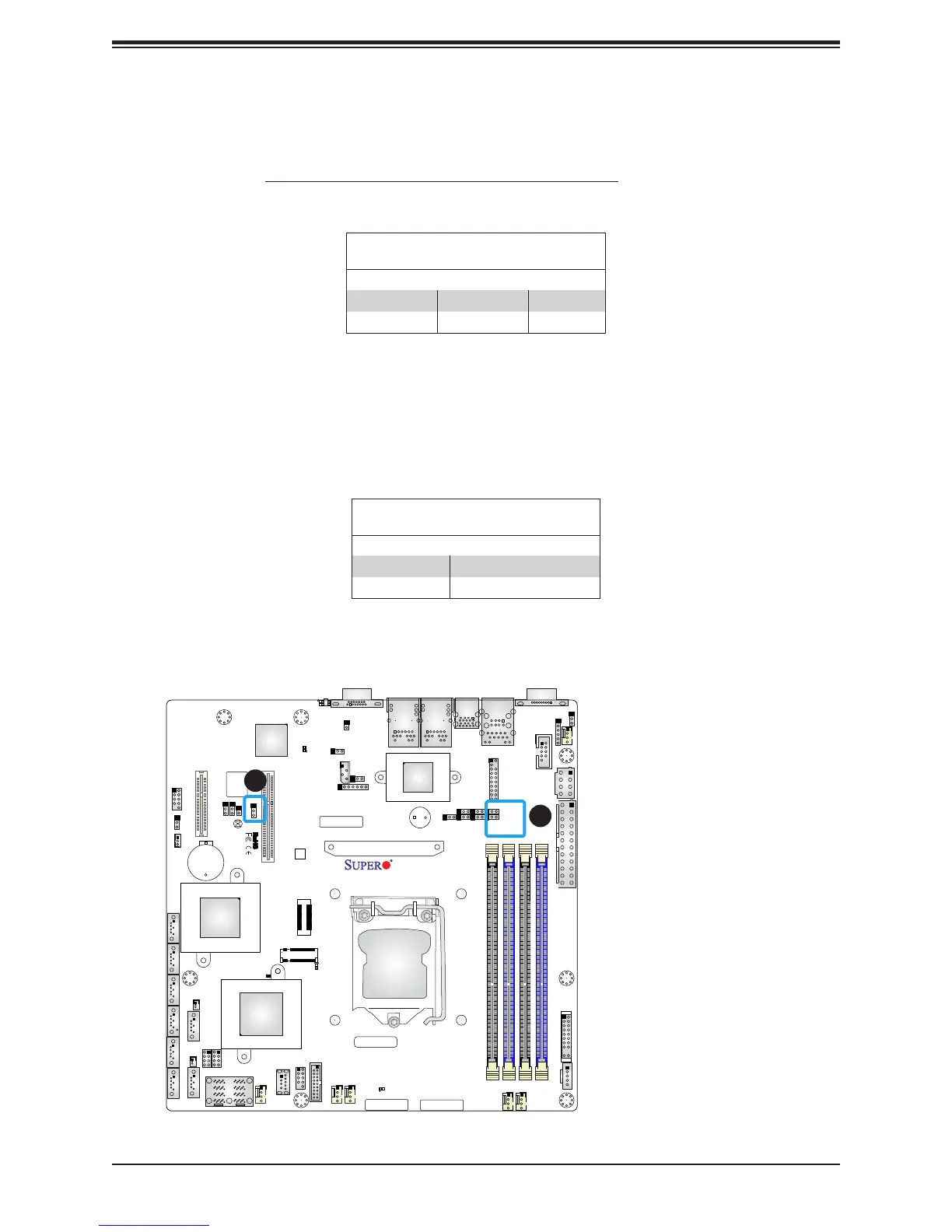
SMBus to PCI Slots
Jumpers JI
2
C1 and JI
2
C2 allow you to connect the System Management Bus (I
2
C) to the
PCI-E/PCI slots. Both jumpers must be set to the same setting (JI
2
C1 controls the data and
JI
2
C2 controls the clock). The default setting is Disabled.
SMBus to PCI Slots
Jumper Settings
JI
2
C1 Setting JI
2
C2 Setting Denition
Pins 1-2 Pins 1-2 Enabled
Pins 2-3 Pins 2-3 Disabled
BMC Enabled
JPB1 allows you to enable or disable the BMC (Baseboard Management Control) chip and
the onboard IPMI connection. This jumper is used together with the IPMI settings in the BIOS.
After the BMC is disabled, IPMI health monitoring and remote management functions are no
longer supported.
BMC Enable
Jumper Settings
Jumper Setting Denition
Pins 1-2 Normal (Default)
Pins 2-3 Disable BMC
DESIGNED IN USA
X11SSH-TF
REV:1.01
BAR CODE
SAS CODE
MEGERAC
LICENSE
IPMI CODE
MAC CODE
PRESS FIT
Intel
PCH
LSI3008
(-CTF only)
X550
BT1
JSAS1
JSTBY1
LEDS1
J2
SP1
LE1
LEDBMC
LEDPWR
JPSAS1
JOH1
JL1
JPG1
JBR1
JVRM2
JVRM1
JPME2
JVR1
JPS1
JPB1
JI2C1
JI2C2
JWD1
JPTG1
JSD2
JSD1
FAN5
FANA
FAN3
FAN4
FAN1
FAN2
JUIDB1
JIPMB1
JPI2C1
JD1
JPWR2
I-SGPIO2
I-SGPIO1
I-SATA7
I-SATA6
I-SATA3
I-SATA2
I-SATA1
I-SATA0
JF1
JTPM1
JPWR1
I-SATA5
I-SATA4
MH8
J24
LE3
JBT1
JPCK1
DIMMB2
DIMMB1
DIMMA2
DIMMA1
USB8(3.0)
USB4/5
USB9/10(3.0)
USB2/3
CPU Socket LGA1151
PCH SLOT4 PCI-E 3.0 X2 (IN X4)
CPU SLOT6 PCI-E 3.0 X8
VGA
LAN2
LAN1
USB6/7
(3.0)
USB0/1
IPMI_LAN
COM2
COM1
1
1. SMBus to PCI Slots
2. BMC Enabled
2