25
Chapter 2: Installation
C
A
PRESS FIT
A
BAR CODE
REV:1.01
X12STL-IF
DESIGNED IN USA
BIOS LICENSE
JD1
MH4
MH2
JPL1
JL1
JPME2
I-SATA5
JSD1
I-SATA4
BT1
JSMB1
JPV1
MH1
FAN1
FAN2
JPWR1
MH3
JF1
JPI2C1
FAN3
JUIDB1
JMD1_SRW1
JTPM1
LED1
JBT1
JMD1
JPCIE1
JRF1
FANA
JPG1
JCPLD1
JVRM1
JPL2
JWD1
LED3
LED2
LEDM1
CPU
DIMMB1
CPU SLOT7 PCI-E 4.0 X16
DIMMA1
OH
NIC1
VGA
X
PWR
HDD
LED
PWR
LED
RST
FF
I-SATA0-3
LAN1/2
JF1:
NIC2
ON
USB 6/7(3.2)
USB 2/3
COM
USB 0/1
USB 4/5(3.2)
BMC_LAN
UID
JSD2
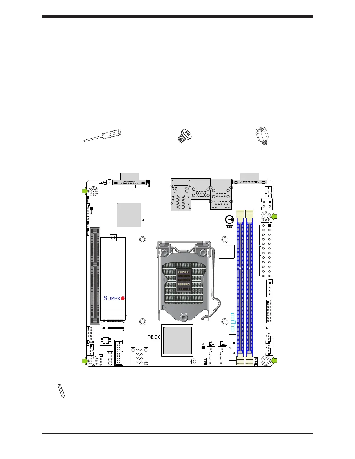
2.3 Motherboard Installation
All motherboards have standard mounting holes to t dierent types of chassis. Make sure
that the locations of all the mounting holes for both the motherboard and the chassis match.
Although a chassis may have both plastic and metal mounting fasteners, metal ones are
highly recommended because they ground the motherboard to the chassis. Make sure that
the metal standos click in or are screwed in tightly.
Location of Mounting Holes
Notes: 1) To avoid damaging the motherboard and its components, please do not use
a force greater than 8 lbf-in on each mounting screw during motherboard installation.
2) Some components are very close to the mounting holes. Please take precaution-
ary measures to avoid damaging these components when installing the motherboard
to the chassis.
Phillips
Screwdriver
(1)
Standos (4)
Only if Needed
Phillips Screws
(4)
Tools Needed

 Loading...


