35
Chapter 2: Installation
BIOS LICENSE
SAN MAC
REV:1.01
X13SEI-TF
MAC CODE
IPMI CODE
DESIGNED IN USA
BAR CODE
+
JPCIE7
JPCIE2
JPCIE1
JPCIE6
JPCIE4
JS1
JI2C_FP1
JNVME2
JNVME1
LEDBMC
LED6
LED7
LED4
JPL3
JPME1
JPL2
JBT1
MH13
MH12
MH10
MH11
BT1
JPFR3
JPFR2
JPFR1
JL1
JSTBY1
JSD1
JSD2
FAN3
FAN4
FAN5
FANAFANB
JNVI2C1
JSEN1
JI2C_EXP1
JIPMB1
JRK1
JUIDB1
JPWR1
JPWR2
MH8
MH7
MH4
MH1
MH2
MH3
MH5
MH6
MH9
JTPM1
SATA8
SATA9
JF1
JNCSI1
JPWR3
JM2_1
JM2_2
BMC
X550
PCH
C741
M.2 NVME
M.2-C1
2-3:DISABLE
JPL1:LAN1
1-2:ENABLE
CMOS CLEAR
M.2 NVME
M.2-C2
JPL3:LAN1/2
JPL2:LAN2
1-2:ENABLE
2-3:DISABLE
2-3:DISABLE
1-2:ENABLE
USB7(3.2 Gen 1)
NVME2/3
NVME0/1
USB0/1
BMC_LAN
USB4/5
(3.2 Gen 1)
LAN1LAN2
VGA
COM1
CPU SLOT1 PCIe 5.0 X8
CPU SLOT2 PCIe 5.0 X8
CPU SLOT4 PCIe 5.0 X16
CPU SLOT6 PCIe 5.0 X16
CPU SLOT7 PCIe 5.0 X8
CPU
LED LEDLED 1
2
FAIL
ON
HDD
X NMI
PWRUID NIC
NIC
PS
PWR
RST
JF1
LEDPWR
RAID KEY-1
SATA DOM POWERSATA DOM POWER
SUPERDOM
SUPERDOM
USB6(3.2 Gen 1)
SATA0-7
TPM/PORT80
CHASSIS INTRUSION
USB2/3
2-3:ME RECOVERY
1-2:NORMAL
JPME1
IPMI
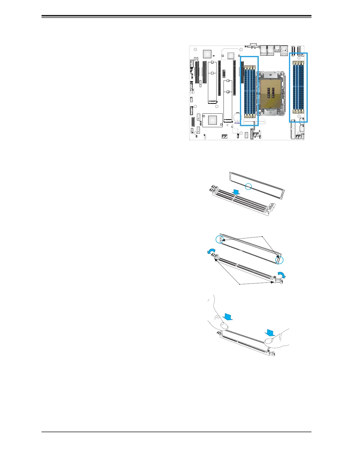
DIMMB1
DIMMA1
DIMMD1
DIMMC1
DIMMG1
DIMME1
DIMMH1
DIMMF1
DIMM Installation
1. Insert DIMM modules in the following
order: DIMMA1, DIMMB1, DIMMC1,
DIMMD1, DIMME1, DIMMF1, DIMMG1,
DIMMH1, and insert the desired number of
DIMMs into the memory slots based on the
Recommended Memory Population Guide
table on page 33.
2. Push the release tabs outwards on both
ends of the DIMM slot to unlock it.
3. Align the key of the DIMM module with the
receptive point on the memory slot.
4. Align the notches on both ends of the
module against the receptive points on the
ends of the slot.
5. Push both ends of the module straight
down into the slot until the module snaps
into place.
6. Press the release tabs to the lock positions
to secure the DIMM module into the slot.
DIMM Removal
Press both release tabs on the ends of the DIMM
module to unlock it. Once the DIMM module is
loosened, remove it from the memory slot.
Release Tabs
Notches
Push both ends
straight down into
the memory slot.