11
Chapter 1: Introduction
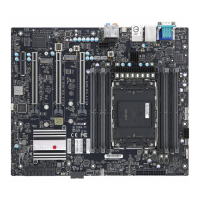
Quick Reference Table
Jumper Description Default Setting
JBT1 Clear CMOS (Onboard) Short Pads to Clear CMOS
JCMOS Clear CMOS (Onboard) Pins 1-2 (Normal)
JPAC1 HD Audio Enable/Disable Pins 1-2 (Enabled)
JPL1, JPL2 LAN1/LAN2 Enable/Disable Pins 1-2 (Enabled)
JPME2 Intel Manufacturing Mode Pins 1-2 (Normal)
JPUSB1 USB6/7 Standby Power Pins 1-2 (Enabled)
JWD1 Watch Dog Function Enable Pins 1-2 (Reset)
LED Description Status
BMC LED BMC Heartbeat LED Blinking Green: BMC Normal
LED8 Status Code LED Digital Readout
M.2-C01/M.2-C02 LED M.2 LEDs for M.2-C01/M.2-C02 Blinking Green: Device Working
Power LED Onboard Power LED Solid Green: Power On
UID-LED Unit Identier (UID) LED Blue On: Unit Identied
Note: The table above is continued on the next page.
 Loading...
