Chapter 2: Installation
2-17
LAN1
®
S
UPER X7DVL-3
FP Control
Fan3
IDE1
Fan4
SATA3
SATA5
PCI 33 MHz
Battery
GLAN
CTRLR
North Bridge
COM1
ATX PWR
8-Pin
PWR
24-Pin
CPU2
South
Bridge
Fan1
SATA2
SATA4
SATA1
SATA0
Slot1
PCI-X 133 MHz
JPL2
Slot5
DIMM 1A (Bank 1)
DIMM 1B (Bank 1)
DIMM
1C
(Bank 1)
DIMM 2A (Bank 2)
DIMM 2B (Bank 2)
DIMM 2C (Bank 2)
JBT1
JCOM2
KB/
Mouse
USB 0/1
5000V
LAN2
Fan5
Fan6
JPWF
JAR
PWR
I
2
C
VGA
Slot6
PCI-X 133 MHz
PCI-E x8
JPG1
JWD
Printer
JPL1
JI
2
C1
JI
2
C2
JWOR
JWOL
Fan2
CPU1
LE2
LE3
LE1
LE5
LE4
SAS0
USB2/3
JPF
Buzzer
ESB2
VGA
CTRLR
T-SGPIO1
JL1
D31
I-Button
SIMLP
Floppy
USB4/5
T-SGPIO0
JD1
BIOS
SAS1
SAS2
SAS3
SAS4
SAS5
SAS6
SAS7
CPU VRM
CPU VRM
Graphics
Memory
S I/O
LSI SAS
Controller
JF1
3-SGPIO1
3-SGPIO0
JPA2
JPA1
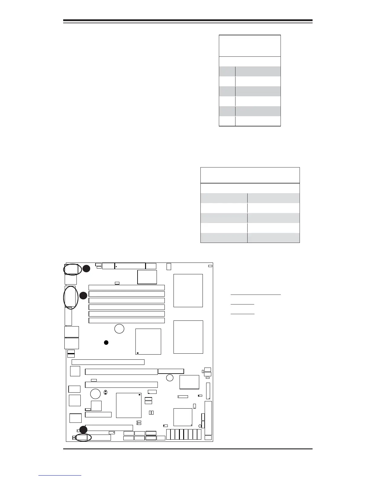
ATX PS/2 Keyboard and
PS/2 Mouse Ports
The ATX PS/2 keyboard and the PS/2
mouse are located at JKM1. See the
table on the right for pin defi nitions.
(The mouse port is above the key-
board port. See the table on the right
for pin defi nitions.)
PS/2 Keyboard and
Mouse Port Pin
Defi nitions
Pin# Defi nition
1 Data
2NC
3 Ground
4 VCC
5 Clock
6NC
Serial Ports
COM1 is a connector located on the
IO Backpanel and COM2 is a header
located at JCOM2. See the table on
the right for pin defi nitions.
Serial Port Pin Defi nitions
(COM1/COM2)
Pin # Defi nition Pin # Defi nition
1 CD 6 DSR
2RD 7RTS
3TD 8CTS
4DTR 9 RI
5 Ground 10 NC
A
B
C
A. Keyboard/Mouse
B. COM1
C. COM2
(Pin 10 is available on COM2
only. NC: No Connection.)