2-30
X7DVL-3/X7DVL-i User's Manual
LAN1
®
S
UPER X7DVL-3
FP Control
Fan3
IDE1
Fan4
SATA3
SATA5
PCI 33 MHz
Battery
GLAN
CTRLR
North Bridge
COM1
ATX PWR
8-Pin
PWR
24-Pin
CPU2
South
Bridge
Fan1
SATA2
SATA4
SATA1
SATA0
Slot1
PCI-X 133 MHz
JPL2
Slot5
DIMM 1A (B
ank 1)
DIMM 1B (Bank 1)
DIMM 1C (Bank 1)
DIMM 2A (Bank 2)
DIMM
2B
(Bank 2)
DIMM
2C
(Bank 2)
JBT1
JCOM2
KB/
Mouse
USB 0/1
5000V
LAN2
Fan5
Fan6
JPWF
JAR
PWR
I
2
C
VGA
Slot6
PCI-X 133 MHz
PCI-E x8
JPG1
JWD
Printer
JPL1
JI
2
C1
JI
2
C2
JWOR
JWOL
Fan2
CPU1
LE2
LE3
LE1
LE5
LE4
SAS0
USB2/3
JPF
Buzzer
ESB2
VGA
CTRLR
T-SGPIO1
JL1
D31
I-Button
SIMLP
Floppy
USB4/5
T-SGPIO0
JD1
BIOS
SAS1
SAS2
SAS3
SAS4
SAS5
SAS6
SAS7
CPU VRM
CPU VRM
Graphics
Memory
S I/O
LSI SAS
Controll
er
JF1
3-SGPIO1
3-SGPIO0
JPA2
JPA1
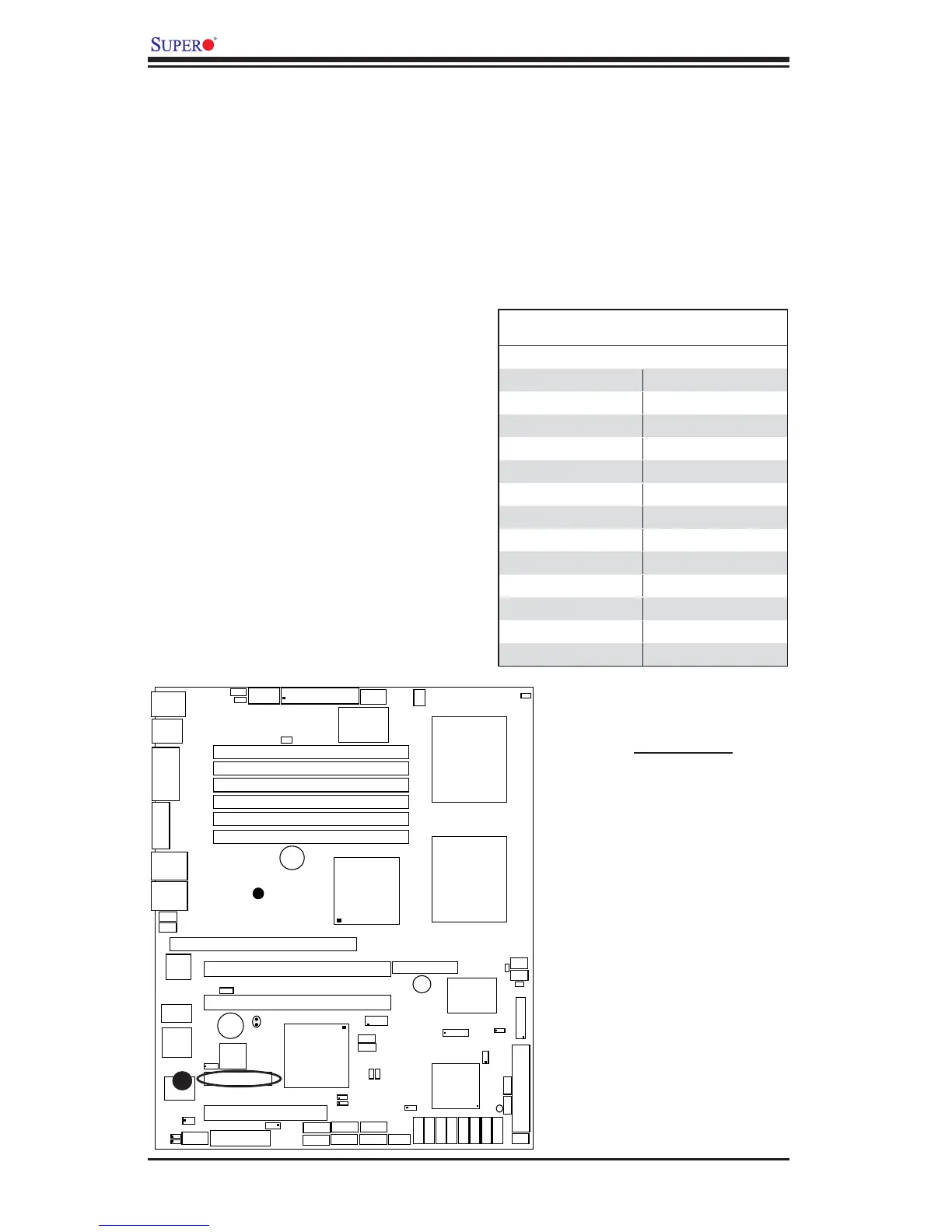
Parallel (Printer) Port
Connector
The parallel (printer) port is located
at J21. See the table on the right for
pin defi nitions.
2-8 Parallel Port, Floppy Drive, SIMLP IPMI and Hard Disk
Drive Connections
Note the following when connecting the fl oppy and hard disk drive cables:
• The fl oppy disk drive cable has seven twisted wires.
• A red mark on a wire typically designates the location of pin 1.
Parallel (Printer) Port Connector
Pin Defi nitions
Pin# Defi nition Pin # Defi nition
1 Strobe- 2 Auto Feed-
3 Data Bit 0 4 Error-
5 Data Bit 1 6 Init-
7 Data Bit 2 8 SLCT IN-
9 Data Bit 3 10 GND
11 Data Bit 4 12 GND
13 Data Bit 5 14 GND
15 Data Bit 6 16 GND
17 Data Bit 7 18 GND
19 ACK 20 GND
21 BUSY 22 Write Data
23 PE 24 Write Gate
25 SLCT 26 NC
A
A. Parallel Port