Chapter 1: Introduction
1-3
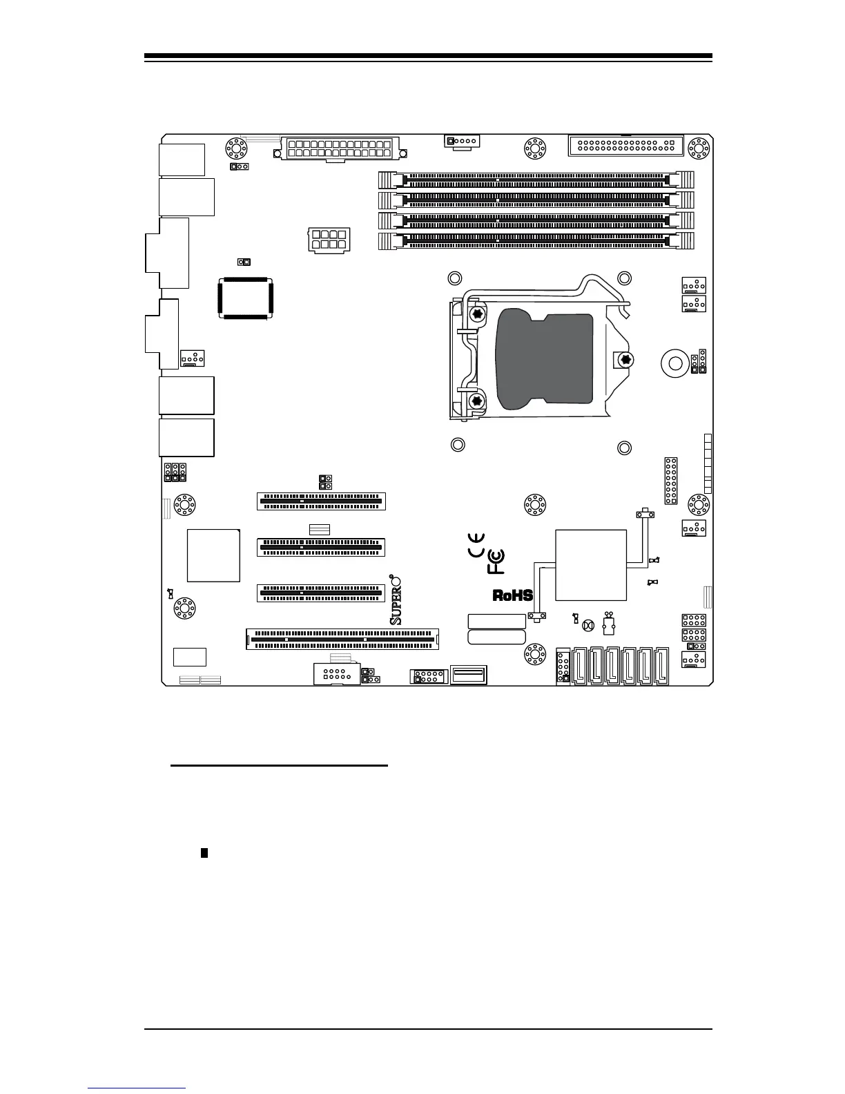
Motherboard Layout
Important Notes to the User
See Chapter 2 for detailed information on jumpers, I/O ports and JF1 front •
panel connections.
" " indicates the location of "Pin 1". •
Jumpers not indicated are for testing only. •
When LE2 (Onboard Power LED Indicator) is on, system power is on. Unplug •
the power cable before installing or removing any components.