1-6
X9SPU-F Motherboard User’s Manual
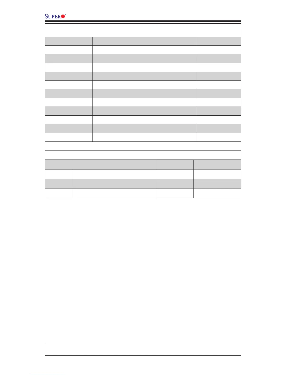
X9SPU-F Motherboard LED Indicators
LED Description Color/State Status
LE7 IPMI Heartbeart Green: Blinking IPMI Normal
LE4 Standby Power LED Green: Solid On Standby Power On
LE5 Unit ID LED Blue: Solid On Unit ID Switch is On
X9SPU-F Motherboard Jumpers
Jumper Description Default
JPG1 Onboard VGA Enable Pins 1-2 (Enabled)
JI2C1~JI2C2 SMB to PCI Slots Pins 1-2 (Enabled)
JWD Watch Dog Timer Reset Pins 1-2 (Reset)
JRF1 x16 PCIe Setting, Force to x8+x8 Pins 1-2 (Auto)
JPL1/JPL2 LAN1/LAN2 Enable/Disable Pins 1-2 (Enabled)
JPB BMC Enable Pins 1-2 (Enabled)
JPME1 ME Recovery Mode Select Pins 2-3 (Disabled)
JPME2 ME Manufacture Mode Pins 2-3 (Disabled)
JUSB1 USB Wake-up Enable (Rear USB Ports) Pins 1-2 (Enabled)
JBT1 CMOS Clear See Chapter 2
J29 BIOS EEPROM Power Pins 1-2 (Enabled)
 Loading...


