1. Never connect SPKR1A- 、SPKR1B- together since they belong to different
NETs.
2. Refer to on-board descriptions for connection details.
3. Both positive and negative speaker outputs are floating and may not be
connected to ground (e.g., through an oscilloscope).
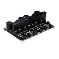
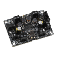
2.4 LED Indicators
This amplifier has 2 LED indicator which is marked as “LED1A” 、“LED1B “. These two
LEDs are used for indicating PWM mode. When powered on, after one second delay,
the two blue LEDs turn ON which indicates that PWM oscillation is present. This
transition delay time is controlled by CSD pin of IRS2092, capacitor CP3.
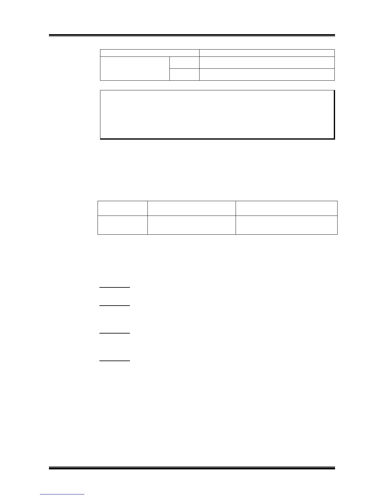
TABLE 2-4 INDICATOR DESCRIPTION
Indicator Mark Indicator Color Description
LED1A,B Blue PWM (presence of low side gate
signal)
2.5 Notes
In order to protect amplifier board and extend its service lifetime, please read the
following warnings carefully since warranties will be voided if you do not observe the
following warnings:
Warning 1:
Quality-related issues caused by potentiometers installed by buyers.
Warning 2:
In order to achieve a better sound quality, please use stable power supply since a bad or
unstable power supply may worsen the sound quality or even cripple the amplifier board.
Warning 3:
Never equip a pre-amplifier to the audio input since the amplifier itself has powerful
amplification ability and a high signal input will burn out the amplifier chip.
Warning 4:
In order to protect amplifier and speaker, please turn the volume output to the minimum
when hooking up the amplifier and you may readjust the volume when you are sure that
the amplifier is functioning properly.
 Loading...