14
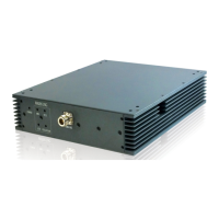
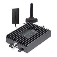
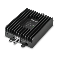
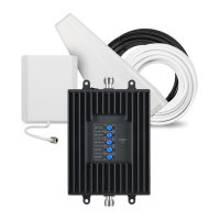
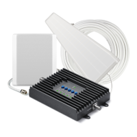
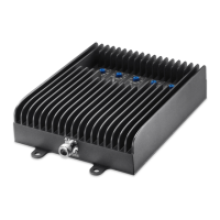
Booster Hardware
Booster Hardware
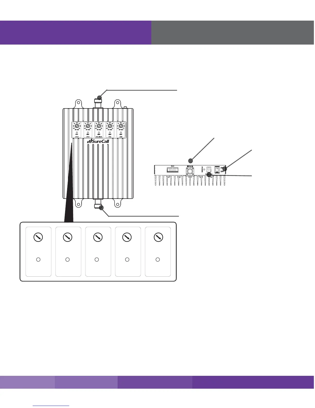
The following image shows the key hardware components on the cellular booster. Refer to this image as
you install your Fusion5s kit components.
Power Jack
Power Switch
Connector to Inside Antenna
N connector to inside antenna
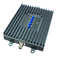
LED Indicators
Please note the following information:
• The booster gain dials or switches should always be at maximum level unless the control light for a specic
frequency band is ashing red or ashing red-yellow. In either case, only reduce gain via dials or switches if
other recommended actions do not resolve the issue.
• As highlighted in the following table, all of the following conditions indicate normal operation: lights o, ashing
yellow, or solid yellow.
• Only the presence of red LEDs indicate an unresolved issue.