10
lci1.com Rev: 03.10.20574-537-8900 CCD-0003622
INSTALLATION
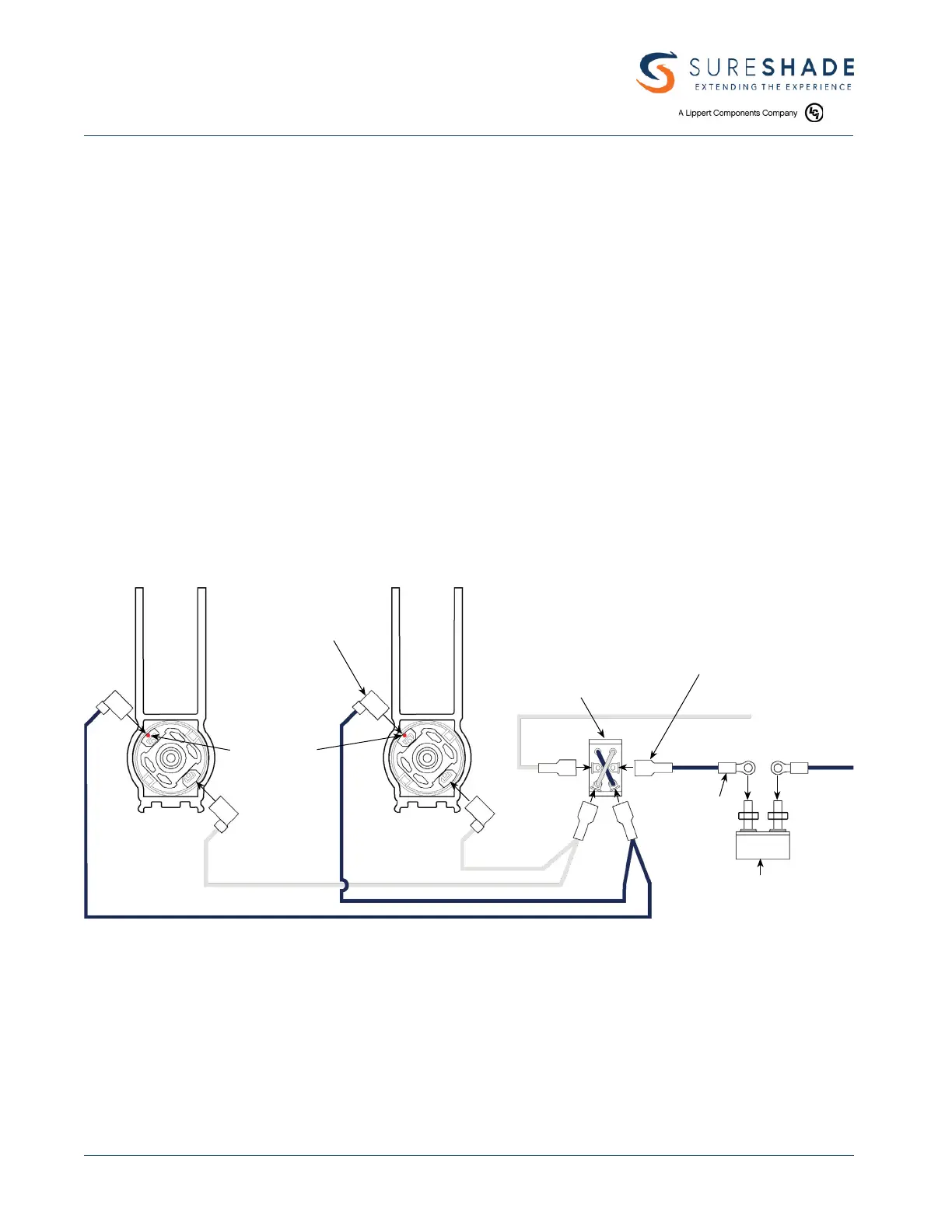
STEP 9 WIRE SWITCH
TOOLS REQUIRED:
1. Wire cutter/stripper
2. Wire crimper
3. Cordless or electric drill or screw gun
4. 1/2" drill bit
PARTS REQUIRED:
A. Control switch
B. Breaker
C. Wire terminals
Locate where on the helm you want the control switch and drill 1/2" hole. Trim excess wire length and connect
the white wire from each actuator to one side of the switch (A) and the dark blue wires to the other side
of the switch (A). Connect positive and negative battery leads and breaker (B) as shown using excess wire
trimmedearlier.
A
B
NOTE RED DOT
ON OR NEAR
ONE MOTOR
TERMINAL
3/16" FLAG TERMINAL
FULLY INSULATED (4) REQ'D
DPDT REVERSING TOGGLE SWITCH
PHILMORE #30 - 125
BATTERY
GROUND (-)
BATTERY
POSITIVE (+)
1/4" SPADE TERMINAL
FULLY INSULATED
(4) REQUIRED
#10 INSULATED
RING TERMINAL
(2) REQUIRED
6 AMP SHORT STOP BREAKER
BUSSMAN #121A06-A2M-HD
NOTE: ALL WIRES TO BE 16 GAUGE
NOTE: A helm switch and RF Remote Control are provided, but both do not need to be installed for the system to
operate. If the helm switch and the RF Remote Control are both installed, refer to the wiring diagram in
that section.
 Loading...