FI SYSTEM DIAGNOSIS 4-33
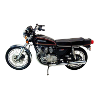
Step 2
1) Crank the engine a few seconds with the starter motor, and
measure the CMP sensor peak voltage at the coupler.
2) Repeat the above test procedure a few times and measure
the highest peak voltage.
CMP sensor peak voltage: 0.7 V and more
(+ B/Y – - B/Br)
1 Peak volt adaptor
09900-25008: Multi-circuit tester set
Tester knob indication: Voltage ()
.
Is the voltage OK?
3) After repairing the trouble, clear the DTC using SDS tool.
(4-26)
YES
• G/Y or Brown wire open or shorted to ground
• Loose or poor contacts on the CKP sensor cou-
pler or ECM coupler (terminal C or T)
• If wire and connection are OK, intermittent trou-
ble or faulty ECM.
• Recheck each terminal and wire harness for
open circuit and poor connection.
• Replace the ECM with a known good one, and
inspect it again.
NO
• Inspect that metal particles or foreign material
stuck on the CMP sensor and rotor tip.
• If there are no metal particles and foreign mate-
rial, then replace the CMP sensor with a new
one.
V
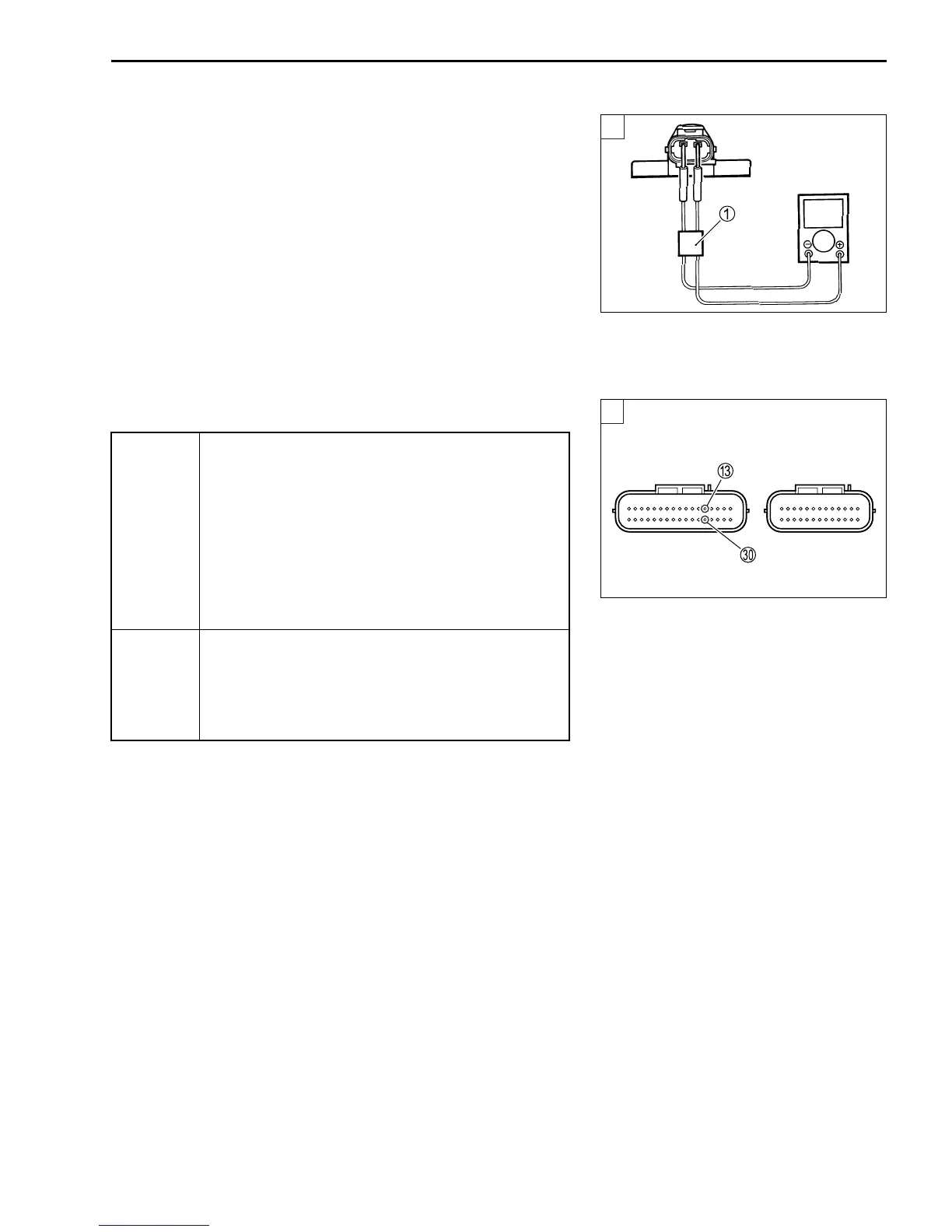
2
ECM couplers (Harness side)
2

 Loading...