FI SYSTEM DIAGNOSIS 4-59
Step 3
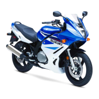
1) Remove the AP sensor.
2) Connect the vacuum pump gauge to the vacuum port of the
AP sensor.
Arrange 3 new 1.5 V batteries in series 1 (check that total
voltage is 4.5 – 5.0 V) and connect - terminal to the ground
terminal 2 and + terminal to the VCC terminal 3.
3) Check the voltage between Vout 4 and ground. Also, check
if voltage reduces when vacuum is applied up to 400 mmHg
by using vacuum pump gauge. (Below)
09917-47011: Vacuum pump gauge
09900-25008: Multi-circuit tester set
Tester knob indication: Voltage ()
Is the voltage OK?
4) After repairing the trouble, clear the DTC using SDS tool.
(4-26)
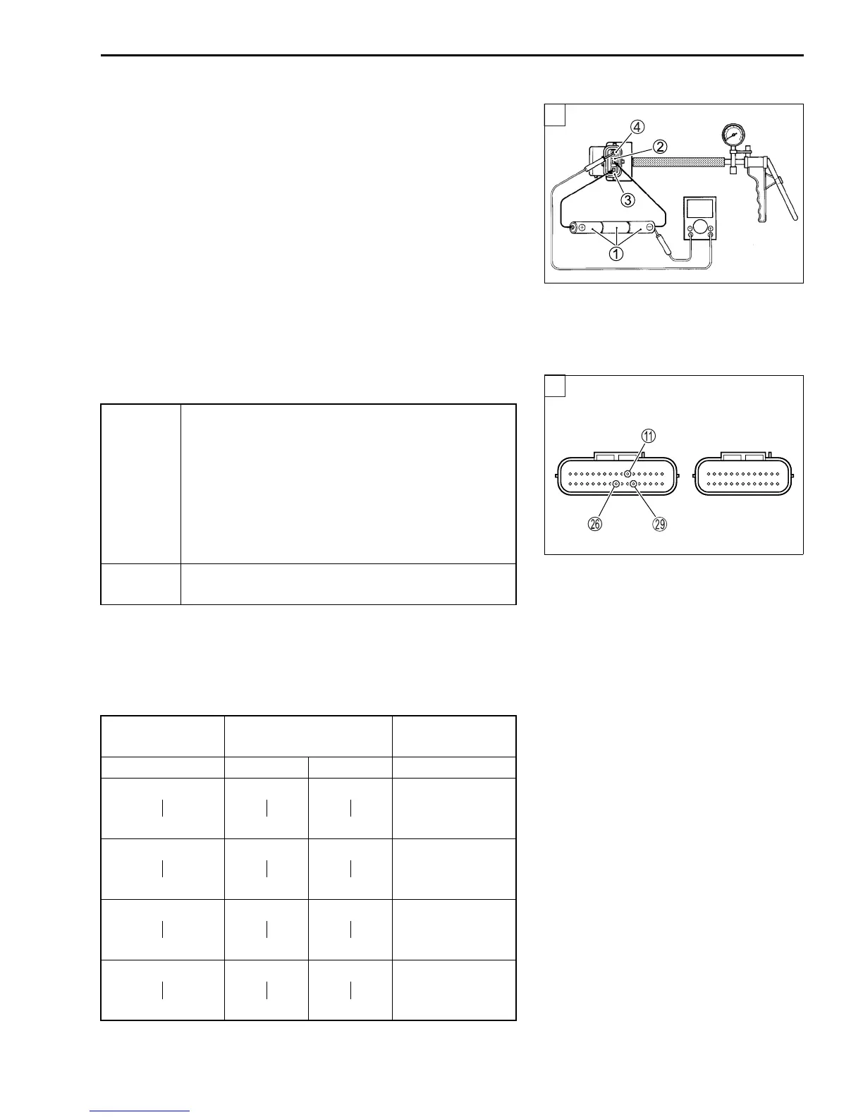
Output voltage
(VCC voltage 4.5 – 5.0 V, ambient temp. 20 – 30 °C)
YES
• R, G/Y or B/Br wire open or shorted to ground,
or poor A, P or S connection.
• If wire and connection are OK, intermittent trou-
ble or faulty ECM.
• Recheck each terminal and wire harness for
open circuit and poor connection.
• Replace the ECM with a known good one, and
inspect it again.
NO
If check result is not satisfactory, replace AP sen-
sor with a new one.
ALTITUDE
(Reference)
ATMOSPHERIC
PRESSURE
OUTPUT
VOLTAGE
(m) (mmHg) kPa (V)
0
610
760
708
100
95
3.1 – 3.6
611
1 524
707
635
94
86
2.8 – 3.4
1 525
2 438
634
568
85
77
2.6 – 3.1
2 439
3 048
567
526
76
70
2.4 – 2.9
V
3
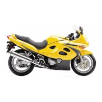
ECM couplers (Harness side)
3

 Loading...