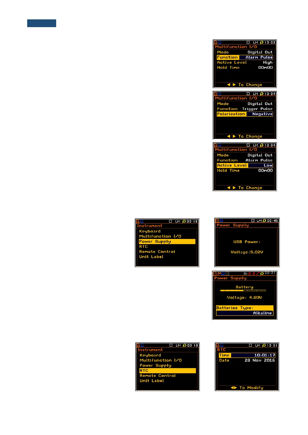
Digital output function selection of the I/O socket
The Function position enables the user to set the function of the digital
output of the I/O instrument’s socket. The socket can be used as the source
of the trigger pulse (Trig. Pulse) which starts the measurement in another
“slave instrument” linked to the “master instrument” or as an alarm signal
which appears there after fulfilling certain measurement conditions
(Alarm Pulse).
Polarisation selection of the digital output signal
The Polarisation position enables the user to select which polarisation of
the signal (Negative or Positive) will be applied.
Active level selection of the digital output signal
The Active Level position enables the user to select which level of the
signal should be treated as a valid one (with “negative” or “positive” logic):
Low or High.
Alarm duration selection
The Hold Time position enables the user to select the minimum duration of
alarm signal.
8.3 Checking the powering of the instrument – Power Supply
The Power Supply position enables the
user to check the power source of the
instrument: internal battery condition,
source and voltage of the external power
supply, and set the battery type for
checking their condition.
The instrument can be powered from four AA rechargeable or standard
alkaline batteries or from the USB interface when its USB Device socket is
connected by means of the cable to a PC or USB power supply such as the
SA 54. The view presented on the display for each powering sources is
different. The current battery voltage is displayed together with its
approximate state (in the graphical form).
8.4 Programming the instrument’s internal Real Time Clock – RTC
The RTC enables the user to programme
the internal Real Time Clock. This clock
is displayed in the different places
depending on the selected presentation
mode.
The window is closed and the instrument
returns to the Instrument list after

 Loading...


