Section IV: Maintenance
4.0.MAI.SL-214
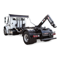
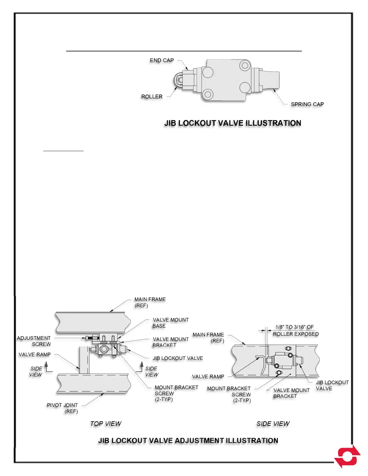
JIB LOCKOUT VALVE INSPECTION & ADJUSTMENT INSTRUCTIONS
All SwapLoader hook-lift
hoists have a jib lockout valve
to prevent accidental
operation of the telescopic jib,
while the hoist is up in a dump
mode. If the jib lockout valve
comes out of adjustment, it
can block the flow of hydraulic
oil to the jib cylinder causing a
reduction in extension or retraction speed to the point of stalling out.
INSPECTION
When a noticeable loss in extension or retraction speed of the telescopic jib is experienced, the
first step should be to inspect the jib lockout valve and valve mount ramp to ensure that they are
adjusted properly and in good working order. The jib lockout valve is located on the inside rail of
the hoist mainframe approximately two-thirds of the way back on the driver side of the hoist (see
Jib Lockout Valve Mount Detail on Pg. 5-2 of the Parts Section of the manual). Visually inspect
the jib lockout valve roller and the condition of the valve ramp on the hoist pivot joint without a
container on the hoist (see illustration on the next page); this is most easily performed with the
hoist back in a dismount mode. If either part shows signs of wear or damage, then replace or
repair as needed.
With the jib lockout valve roller and valve ramp in good condition the next step is to check that
the valve is positioned correctly with respect to the valve ramp. While looking at the roller end of
the jib lockout valve, notice that the roller moves in and out of an end cap. With the hoist pivot
joint in the down position, or horizontal to the hoist mainframe, the valve ramp should be in
contact with the jib lockout valve roller. The roller should be depressed by the valve ramp so
that 1/8” to 3/16” of the roller is exposed from the end cap (see illustration below).