W3.260419
We reserve the right to alter specifications. 27www.swegon.com
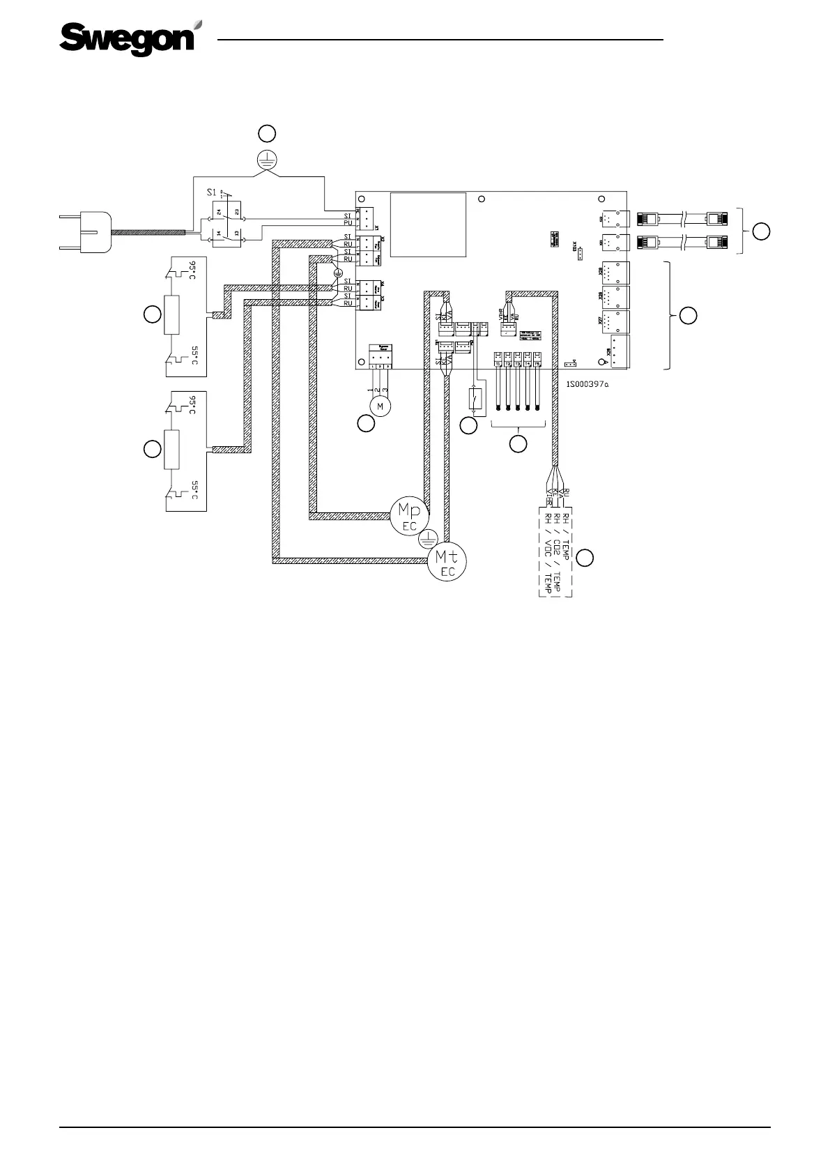
7.6 Electrical wiring diagram
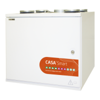
7.6.1 W3
1. Temperature sensor, see the Control diagram
2. Connector for the connection of the Smart control
panel or Smart cooker hood, which are sold as
accessories.
3. External electrical connections. See the sec-
tion “Control functions with optional items of
equipment”.
4. Service switch
5. Preheating air heater (1 000 W / 500 W)
6. Post heating air heater 500 W
7. Damper motor
8. Smart sensor package
RH
RH + CO
2
(accessory)
RH + VOC (accessory)
9. Switch for summer bypass damper
X16
X15
X14
X12
X10
X8
T1
X29
INPUT 230V 10A
1
T4T1 T5
SEC / SEM
T3T2
4
5
6
7
3
8
2
SET 2
SET 1
5 V / 24 V
IO 2
IO 1
GND
9
UI
UI
 Loading...