4.9.2 Wiring with frequency converters
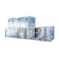
Typical wiring diagram:
Frequency converter with load measuring device, safety
switch and PTC resistor.
Consider the following if frequency converters are
used:
1. The fan motor must be designed for operation with a
frequency inverter.
2. The motor must be protected against overloading and
heating; i.e. have a PTC resistor, for instance. A switch-
type motor protection with bimetallic trip is not appro-
priate.
3. Shielded motor – PTC resistor cables must be run to the
frequency inverters.
4. The motor and fan must absolutely not exceed the max.
permissible speed.
5. In other respects, we refer to the maintenance instruc-
tions from each individual manufacturer of frequency
inverters.
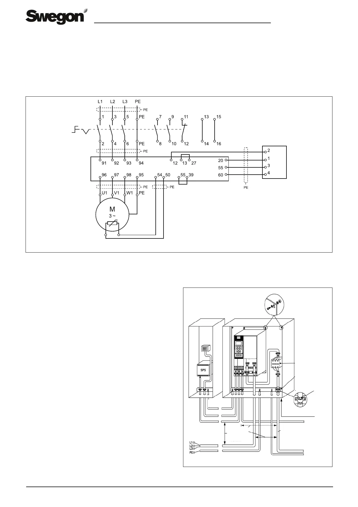
Example: EMC-compatible installation
Aux. contactor
Pressure sensor
PLC etc. Casing plate
Min. 16 mm
2
equalizing cable
Control lines
Line voltage
Min. 200 mm
between control
lines, motor cables
and power cables
Output relay
Earthing strip
Remove the
cable insulation
Mount all the cables on
one side of the plate
Motor thermistor
Motor cables
Motor
PE: Min. 10 mm
2
Min. 10 mm
2
EN.SILVER.110322
The company reserves the right to make design changes without prior notice.
14 www.swegon.com
 Loading...