ELECTRICS
80
TECHNICAL DATA AND APPROVALS
5 Technical Data & Approvals
5.1 Equipment – EC601, EC602, EC651, EC620, EC630 & PX300 Control Equipment
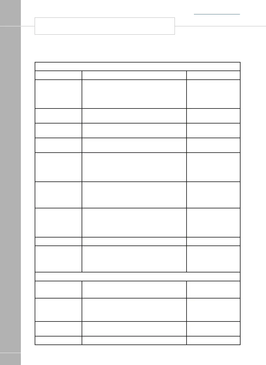
Outline Specification
INPUT 230V 230 Volts / 0 to 16 Amps + / - 10%
OUTPUT 230V RCD protected, 2 x MCB outputs of 10A &
1 x MCB output of 16A
Separate switched channels for heating
system and charger
INPUT 12V 2 x 20A battery inputs via 2 x 4 way
connectors
SOLAR INPUT 1 x Dedicated solar panel input (20 to 150W
panel) via a 2 way connector
OUTPUT 12V 25A total output via multiple switched channels
protected by 13 fused outputs
Integrated
CHARGER
Input 220-240 Volts AC +/- 10%, Frequency
50 Hz +/- 6%, Current 3A max.
DC Output 13.6 to 14.4 Volts nominal,
Current 25 Amps max (300 Watts).
Signal INPUT 4 x Fresh water level, 4 x Waste water level,
1 x Engine running, plus multiple vehicle
connections, sensor inputs for temperature &
humidity
Fresh water negative
sensed
Waste water negative
sensed
Data IN / OUT CANBUS Data communication and power to
Control Panel via 6 way connector
CI-Bus Data communication to CI-Bus enabled
devices via RJ11/12 connector
IP rating IP31
Operating
temperature
Ambient 0 to 35° Celsius
Charger case temperature with full load
65° C Max
Automatic shutdown
and restart if
overheated /
overloaded
Dimensions
EC601 & EC651
PSU
Overall size (HxWxD) 180 x 305 x 135mm
Clearances 75mm above, 50mm left & right
Weight 3.8 Kg
EC620 Control
Panel
Overall size (HxWxD) 93 x 180 x 32mm
Cut-out size (HxW) 82 x 165mm
Fixing centres 166mm
x 26MM
Weight 150 g
EC630 Comms
Module
Overall size (HxWxD) 55 x 116 x 85mm Weight 550g
EC640 Sensor Overall size (HxWxD) 60 x 27 x 14mm Weight 80g
Back to section menu