6. ENGINE REMOVAL
6-13
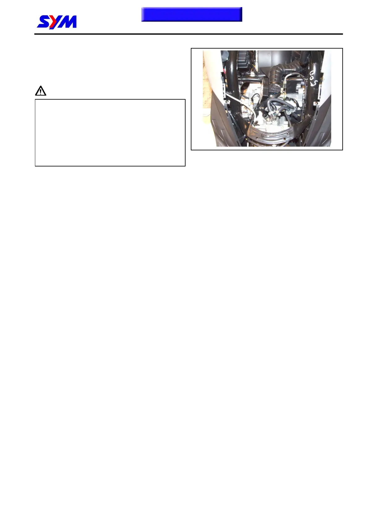
Engine Installation
Check if the bushings of engine suspension
parts and shock absorber for damage.
Install engine in the reverse procedures of
removal.
Caution
● Pay attention to foot & hand safety as engine
installation to avoid hurting.
● Do not bend or twist wires.
● Cables wires have to be routed in
accordance with original layout.
● Small-end bearing ring has to forward to
inside (bearing) as assembling the swing
arm.
Torque value:
Engine hanger locknut 4.0~5.0kgf-m
Rear cushion upper bolt 3.5~4.5kgf-m
Rear cushion lower bolt 2.4~3.0kgf-m
Rear wheel shaft locknut 11.0~13.0kgf-m
To this chapter contents

 Loading...