DOC06501_Revision F
ATS-6501 Users Guide
19
within 100nSec. The ATS-6501 outputs will now be accurate to the coarse calibration accuracy
specified in Appendix A.
ATS-6501>antenna_delay 1.185E-7
OK
ATS-6501>settings gps:antenna_delay
[antenna_delay] 1.185000000000000e-07
2.5 On Time Point (OTP)
The OTP of a system is defined as the point at which the timing signals coincide with
UTC(USNO). Typical systems use distribution amplifiers and cabling to distribute timing signals
from a single source to multiple users. This distribution network will delay the timing signals and
affect their accuracy. For this reason it is important to select an appropriate OTP so that the
desired timing signals are accurate when they reach the user.
Section 2.5 calibrates the ATS-6501 assuming that the OTP of the system is the rear
panel of the ATS-6501. This is not generally a convenient location for the OTP of the system
because
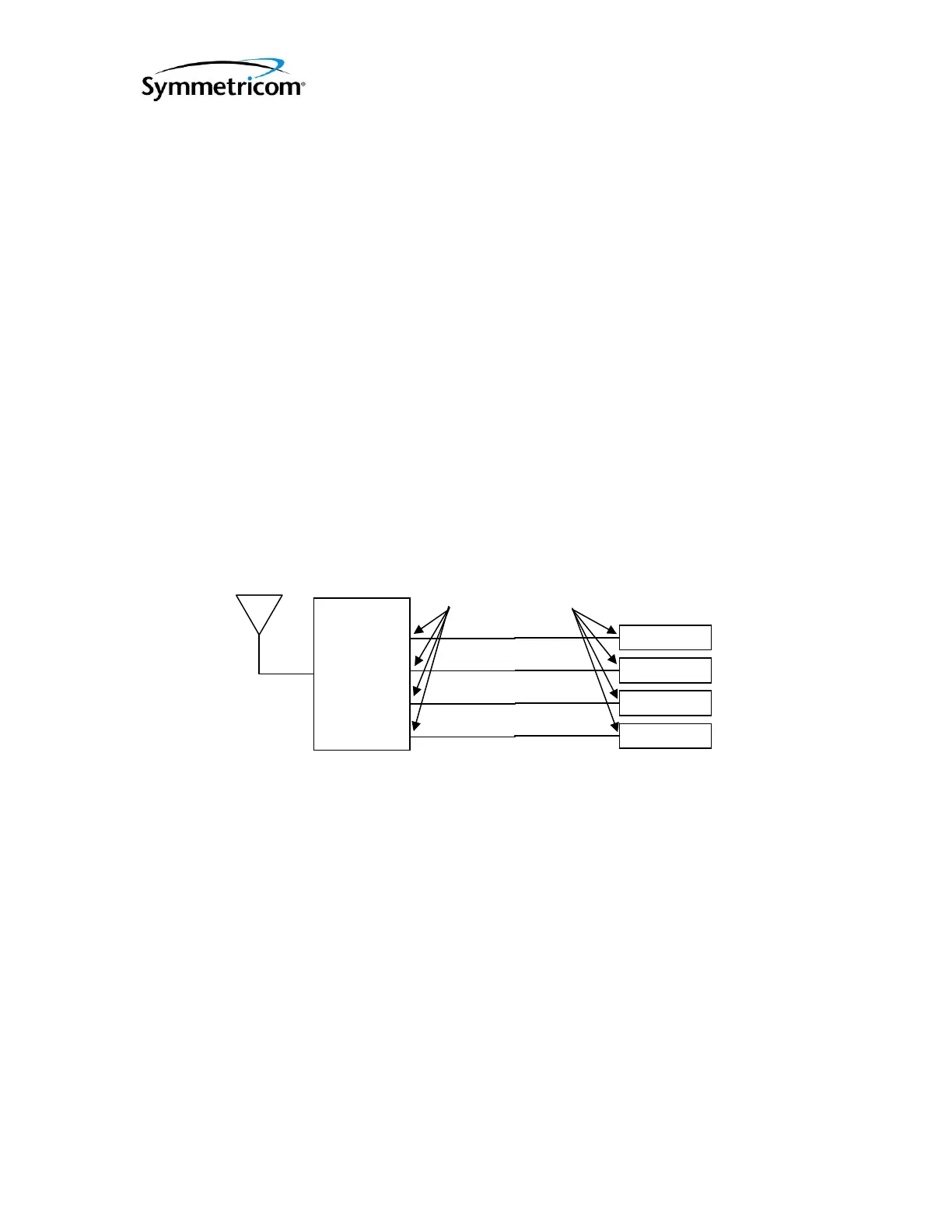
there will be a delay associated with the distribution of the signals to the user. Figure 2-5
illustrates how to move the OTP of the system from the rear panel of the ATS-6501 to the user
inputs. In moving the OTP of the system it is imperative that the distribution delays from the
ATS-6501 to each of the users is equal. This will ensure that all users receive accurate timing
signals.
Once the delay of the distribution network is known the OTP of the system can be shifted
from the output of the ATS-6501 to the input of user equipment. Equation 2-4 is used to calculate
the antenna_delay value that should be entered into the system to adjust the OTP. The
Distribution_Delay is the measured delay of the timing distribution network as shown in Figure
3-2. The ATS_6501_Delay is the delay calculated in Equation 2-2 or the calibrated delay given
by Symmetricom.
(seconds)_(seconds)ATS6501_LAYANTENNA_DE DelayonDistributiDelay
Eq. 2-4
2.6 Using an External Frequency Reference:
Users may decide to provide an EXTERNAL frequency reference to the ATS-6501. The
external frequency reference may be monitored by the ATS-6501 via RS232 through either of the
USB Connectors on the rear of the unit (OP001). The Symmetricom 5071A is the only model
ATS 6501
User 1
User 2
User 3
Fi
ure 5 Timin
S
stem Dia
ram
User 4
PPS Output 1
PPS Output 2
PPS Output 3
PPS Output 4
OLD OTP
NEW OTP
Delay 1
Delay 2
Delay 3
Delay 4
Delay 1 = Delay 2 = Delay 3 = Delay 4 = Distribution_Delay
 Loading...