6000-100Ch2.fm Rev. D TimeVault™ User’s Manual 2-15
Cabling Chapter 2: Installation and Start-Up
2.2 Cabling
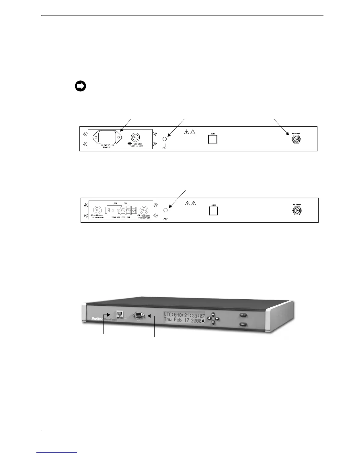
Refer to the figures below for TimeVault connector locations. The numbers in the
drawing refer to that connector’s position in Table 2-1.
Figure 2-3: TimeVault Back Panel Cabling Illustration (AC Mains)
Figure 2-4: TimeVault Back Panel Cabling Illustration (–48 VDC)
For the –48 VDC model, connect the rear panel chassis ground to your system ground, the
positive connection from the power supply to the “+” of the rear panel terminal strip, and
the negative connection from the power supply to the “–” of the rear panel terminal strip.
Figure 2-5: TimeVault Front Panel Cabling Illustration
Connect the cables in the order listed in Table 2-1 below. In order to avoid network addressing
conflicts, be sure to configure network parameters before connecting the Ethernet cable.
–36 to –60 VDC Terminal Strip (4)
12 V Antenna (1)
Chassis Ground (3)
100-240 VAC Power Input (4)
12 V Antenna (1)
Chassis Ground (3)
ACTS Modem (2)
ACTS Modem (2)
Serial Port (6)
NET Port (5)