1-7-7 T2127EA
9. White Balance Adjustment
Purpose: To mix red, green and blue beams correctly
for pure white.
Symptom of Misadjustment: White becomes bluish
or reddish.
Note: Use service remote control unit
1. Operate the unit more than 20 minutes.
2. Face the unit to the east. Degauss the CRT using
a degaussing coil.
3. Input the White Raster (APL 100%).
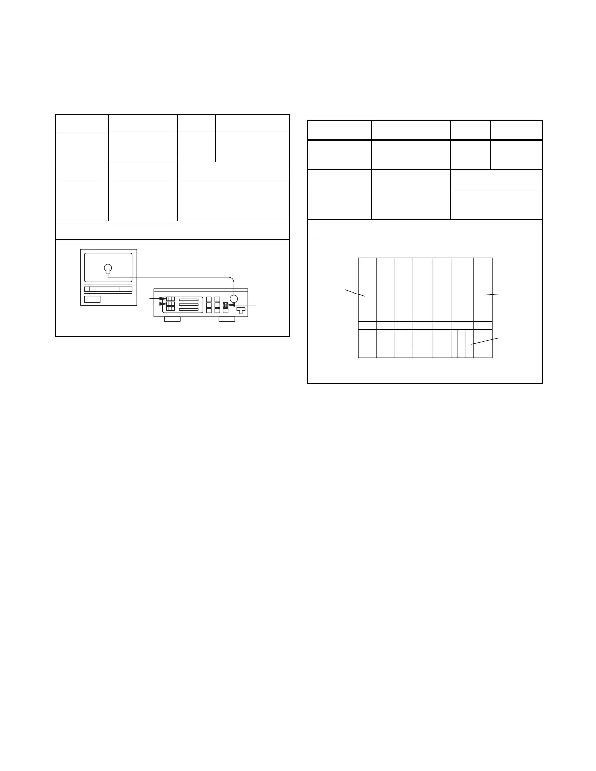
4. Set the color analyzer to the CHROMA mode and
after zero point calibration, bring the optical recep-
tor to the center on the tube surface (CRT).
5. Enter the Service mode. Press [VOL p] button on
the service remote control unit and select "C/D"
mode. (Display changes "C/D", "7F", "SLP R" and
"MONO" cyclically when [VOL p] button is
pressed.)
6. Press [4] button on the service remote control unit
for Red adjustment. Press [5] button on the service
remote control unit for Blue adjustment.
7. In each color mode, press [CH. o / p] button to ad-
just the values of color.
8. Adjust Red and Blue color so that the temperature
becomes 9200K (x: 286 / y: 294) ±3%.
9. At this time, re-check that horizontal line is white. If
not, re-adjust Cut-off Adjustment until the horizon-
tal line becomes pure white.
10. Turn off and on again to return to normal mode. Re-
ceive APL 100% white signal and confirm that Chro-
ma temperatures become 9200K (x: 286 / y: 294)
±3%.
Note: Confirm that Cut Off Adj. is correct after this
adjustment, and attempt Cut Off Adj. if needed.
10. Sub-Brightness Adjustment
Purpose: To get proper brightness.
Symptom of Misadjustment: If Sub-Brightness is
incorrect, proper brightness cannot be obtained by
adjusting the Brightness Control.
Note: SMPTE Setup level --- 7.5 IRE
1. Enter the Service mode. (See page 1-7-1.)
Then input SMPTE signal from RF input.
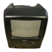
2. Press [PICTURE] button. (Press [PICTURE] button
then display will change BRT, CNT, COL, TNT, V-
TNT, and SHP). Select BRT and press [CH. o / p]
buttons so that the bar is just visible (See above
figure).
3. Turn the power off and on again.
Test Point Adj. Point Mode Input
Screen
CH. o / p
buttons
RF
White Raster
(APL 100%)
Tape M. EQ. Spec.
---
Pattern
Generator,
Color analyzer
See below
Figure
Color Anal
zer
Fig. 6
Test point Adj. Point Mode Input
---
CH. o / p
buttons
---
SMPTE
7.5IRE
Tape M. EQ. Spec.
---
Pattern
Generator
See below
Figure
Black
White
This bar
just
visible
Fig. 7