20
Synrad Firestar OEM v30 reference guide
Controls and indicators
AVOID EXPOSURE
Invisible laser radiation
is emitted from
this aperture.
8
9
6
5
4
INTERFACE
LASE
RDY
PWR
AB
3
2
7
SA Model Shown
1
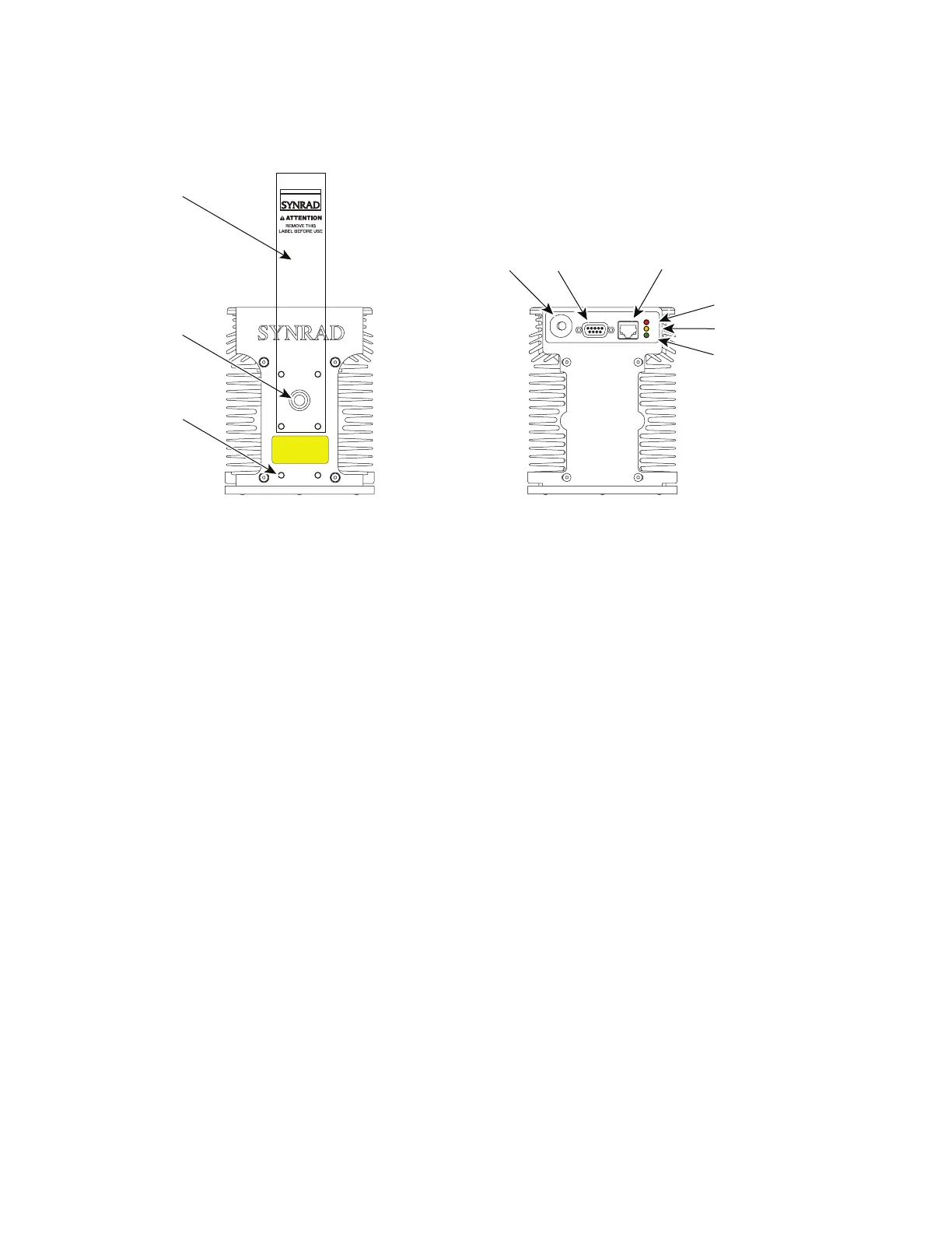
Figure 7 OEM v30 controls and indicators
1
Aperture Seal – prevents dust from damaging the output coupler during shipping. Remove the red self-adhesive label
before applying power to the laser.
2
Laser Aperture – provides an opening in Firestar’s front panel from which the beam exits.
3
Optical Accessories Mounting – provides six threaded holes (8–32 UNC) for mounting optional beam delivery com-
ponents available from SYNRAD. Because excessive weight may damage the laser, consult SYNRAD before mounting
components not specifically designed as Firestar options. Refer to the Firestar OEM v30 package outline drawings for
mounting hole dimensions.
Note: When mounting optical components to the OEM v30, excessive fastener length may damage the laser. See the
package outline drawings for important information about accessory mounting hole depth.
4
DC Power Cables – receives 30 VDC from the DC power supply. The cables are manufactured with #12 AWG wire
and measure 1 meter (40 inches) in length. The red (positive) cable contains a replaceable in-line fuse. If fuse replace-
ment is required, replace it with a Bussman ABC20 or a Littelfuse 314020 fuse.
5
Interface A (DB-9) Connector – provides a connection point for auxiliary output power as well as input and output
signals. Refer to the Technical Reference section for DB-9 interface details and pinouts.
6
Interface B (RJ45) Connector – provides a connection point for auxiliary output power as well as input and output
signals. Refer to the Technical Reference section for RJ45 8-8 interface details and pinouts.
7
LASE Indicator – illuminates red to indicate that the OEM v30 is actively lasing. The LASE indicator is off when
tickle pulses are being generated and illuminates red when PWM Command signal pulses are long enough to produce
laser output.
8
RDY Indicator – illuminates yellow when the laser is enabled, indicating that lasing will begin when a Command
signal is applied.
9
PWR Indicator – illuminates green when +30 VDC power is applied to the laser.