SYNTHES 11
DHS/DCS Standard System
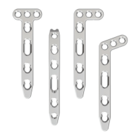
DHS trochanter stabilizing plate
11b
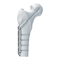
Position DHS trochanter stabilizing plate on DHS plate
Insert the DHS/DCS screw and DHS plate as described in
steps 1 to 10. If an anti-rotation screw is to be used,
the DHS/DCS screw must be inserted in a slightly more caudal
direction than for the standard technique.
Fix the DHS plate by inserting a cortex screw 4.5 mm
through the second proximal plate hole and insert a new
guide wire.
Locate the DHS trochanter stabilizing plate flush against the
DHS plate.
Note: The scooped section of the DHS trochanter
stabilizing plate can be shaped beforehand using parallel
flat-nosed pliers or a bending iron.
12b
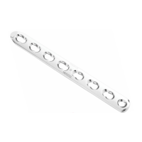
Fix plates
Fix the DHS trochanter stabilizing plate and the DHS
plate using cortex screws 4.5 mm of the appropriate
length.
Depending on the indication, individual fracture
fragments of the greater trochanter can be fixed against the
scooped section of the DHS trochanter stabilizing plate
using screws 4.0 mm or cerclage wires.
13b
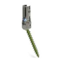
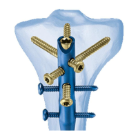
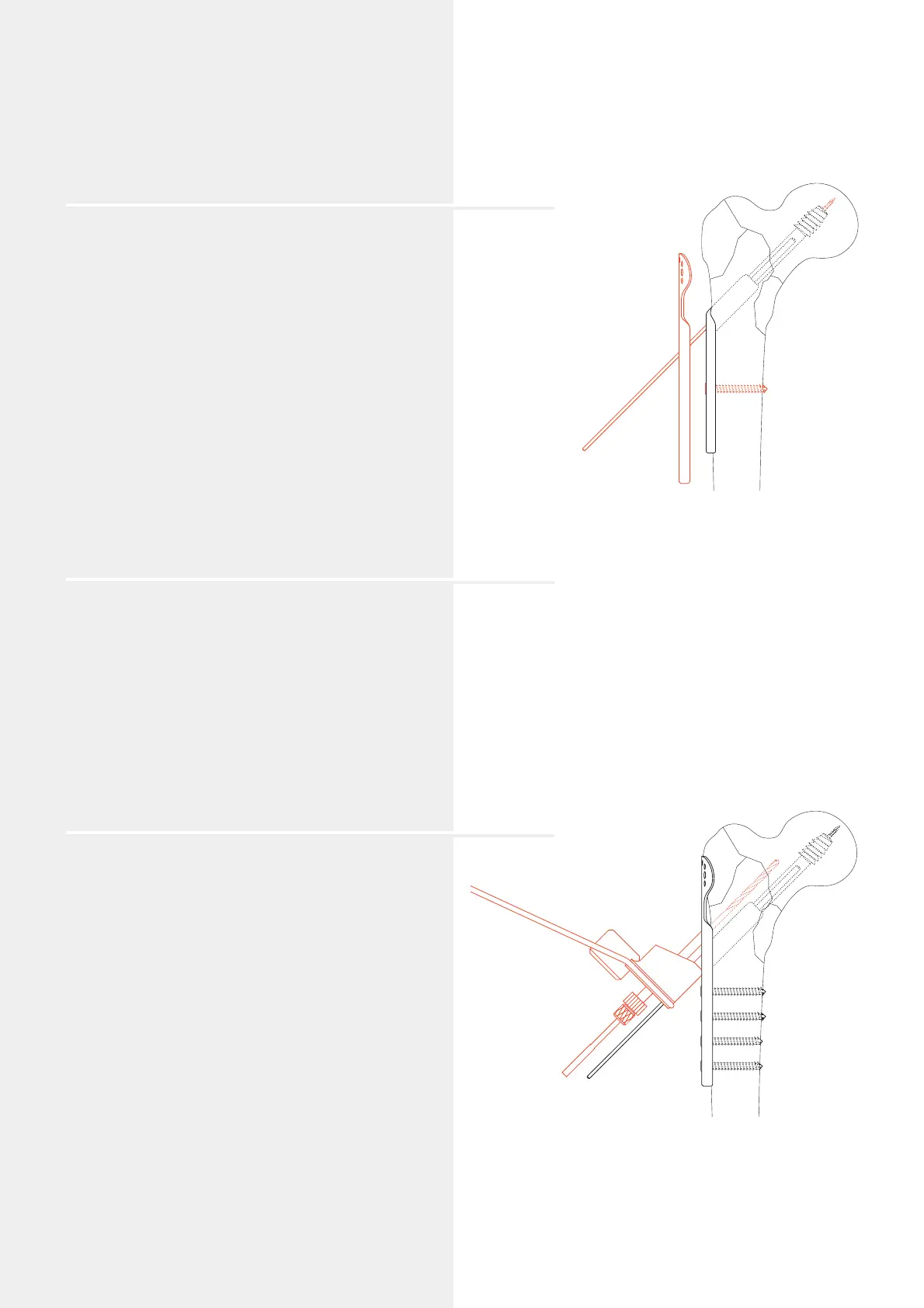
Insert anti-rotation screw (option)
An anti-rotation screw can be inserted cranially and parallel
to the DHS/DCS screw.
Cancellous bone screws 6.5 mm (with the Drill Sleeve
System 338.730 and 338.740), cannulated screws 7.0 mm
(with the Drill Sleeve System 338.720 and 338.740) and
cannulated screws 7.3 mm (with the Drill Sleeve System
338.731 and 338.740) can be used.
Position the DHS Parallel Drill Guide (338.750) over the
guide wire (aperture with the 0 mark). Insert the appropriate
drill sleeve system in the 12 mark of the guide. For the
cancellous bone screws 6.5 mm tap a threaded hole. For
cannulated screws 7.0 mm and 7.3 mm, insert a
guide wire.
Insert the screw according to the usual insertion technique.
Remove the guide wire.