acceptable for your installed distance. The sensitivity of
the detector can be set only when the housing is removed
and the detector is not in the fine adjustment step of the
alignment mode, indicated by the illumination of the dual
digital display. To set the sensitivity depress the sensitivity
button one time. See Figure 10. Once the switch is pressed
the digital display will illuminate and read the current
sensitivity setting in percent obscuration. To change the
sensitivity continue to depress the sensitivity switch until
the desired setting is achieved. The digital display will turn
off automatically if no further switch presses occur.
Sensitivity
Setting
%
Obscuration
Display
Reading
Acceptable
Distance
Between
Detector
and
Reflector
(Feet)
Acceptable
Distance
Between
Detector
and
Reflector
(meters)
Level 1 25 25 16.4 to 120 5.0 to 36.6
Level 2 30 30 25 to 150 7.6 to 45.7
Level 3 40 40 60 to 220 18.3 to 67
Level 4 50 50 80 to 328 24.4 to 100
Acclimate
Level 1
30 to 50 A1 80 to 150 24.4 to 45.7
Acclimate
Level 2
40 to 50 A2 80 to 220 24.4 to 67
In addition to the four standard sensitivity selections the
detector has two Acclimate settings. When either of these
settings is chosen the detector will automatically adjust its
sensitivity using advanced software algorithms to select the
optimum sensitivity for the environment. The sensitivity
will be continuously adjusted within the ranges specified
in the chart above.
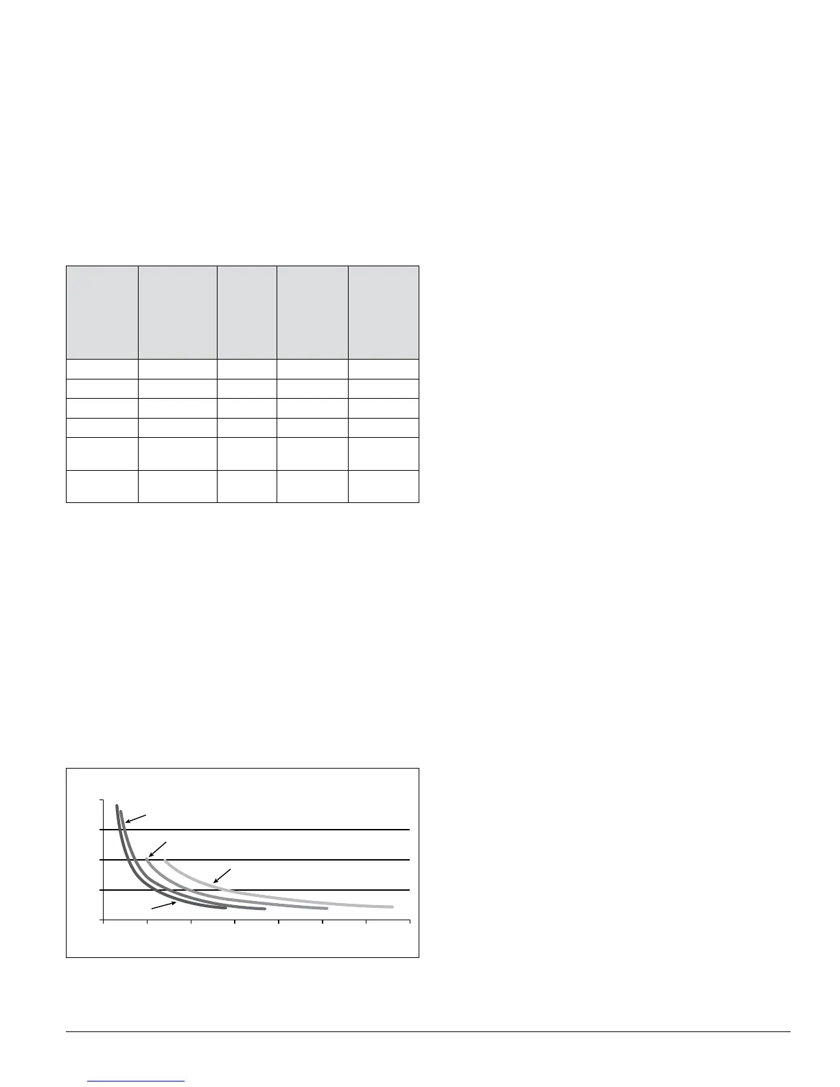
Sensitivity
Total obscuration can be converted to percent per foot,
assuming uniform smoke density for the entire length of
the beam. The charts below converts total obscuration to
percent per foot for all acceptable sensitivity settings.
2.0
1.5
1.0
0.5
0.0
0
25% Setting
30% Setting
40% Setting
50% Setting
50 100 150 200 250 300 350
Sensitivity in %/Ft. vs. Distance
(assumes uniform smoke distribution)
Distance in Feet
Obscuration (%/Ft.)
C0268-00
Sensitivity Testing
NOTE: Before testing, notify the proper authorities that the
smoke detector system is undergoing maintenance,
and therefore the system will be temporarily out
of service. Disable the zone or system undergoing
maintenance to prevent unwanted alarms.
Detectors must be tested after installation and following
periodic maintenance. The sensitivity of the FSB-200/FSB-
200S may be tested as follows:
NOTE: Before testing the detector, check for the presence
of the flashing green LED at the receiver, making
sure not to disturb or block the beam. If it does not
flash and the detector is not in trouble or alarm,
power has been lost to the detector (check the wir-
ing).
A. Calibrated Test Filter
The sensitivity of the detector can be tested using an
opaque material to cover the reflector by an amount indi-
cated by the graduated scale on the reflector. (Due to the
high optical efficiency of the reflector the selection of the
opaque material used to block the reflector is not critical.
Acceptable materials include, but aren’t limited to, this
manual or the cardboard packaging inserts.)
Refer to Figure 14 for this procedure.
1. Verify the sensitivity setting of the detector in % obscura-
tion. See the Sensitivity Selection section of this manual
for sensitivity determination if sensitivity is unknown.
2. Place the blocking material over the reflector, lining it
up with the graduated marks that are 10 less than the
detector’s setting in % obscuration. The detector should
not alarm or fault. Keep the material in place for a mini-
mum of 1 minute.
3. Place the blocking material over the reflector lining it
up with the graduated marks that are 10 more than the
detectors setting in % obscuration. The detector should
enter alarm within 1 minute.
N200-25-00 11 I56-2424-04R