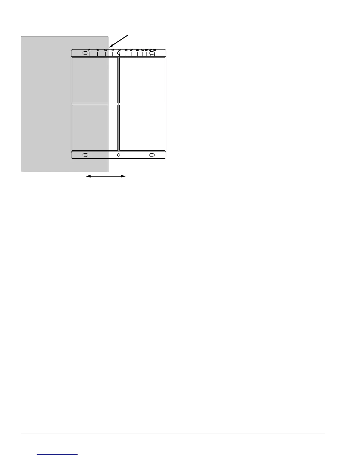
Figure 14. Reflector Test Card Procedure
LINE UP EDGE OF
TEST CARD WITH
APPROPRIATE
OBSCURATION LEVEL
MOVE TEST CARD
TO DESIRED AMOUNT
OF OBSCURATION
C0267-00
4. The detector can be reset with the reset switch on the
detector unit or remote reset.
5. Notify the proper authorities that the system is back on
line.
If the detector fails this test several steps should be taken
to determine if the detector is faulty or simply needs to be
re-adjusted before returning the unit. These steps include:
1. Verify all wiring connections and appropriate power is
applied to the detector.
2. Verify that the optical line of sight is free from obstruc-
tions and reflective objects.
3. Apply the maintenance procedure in this manual.
Repeat the test procedure. If the detector still fails the
test procedure proceed with step 4.
4. Repeat the alignment procedure in this manual. If the
alignment procedure is successful repeat the test pro-
cedure. If the detector still fails the test it should be
returned.
NOTE: For the FSB-200S the external power supply must
be connected for the test switch to work.
B. Test Switch
The detector can be tested using the local test switch on
the transmitter/receiver unit or remotely using the remote
test station.
The remote test station, RTS451 or RTS451KEY, can be used
with the FSB-200/FSB-200S beam smoke detector. Follow
instructions included with the test station for proper use.
See Figure 8 (Remote Test Station) for wiring diagram.
The FSB-200S is equipped with an integral sensitivity test
feature that consists of a calibrated test filter attached to
a servo motor inside the detector optics. When a test is
initiated using the remote test station or local test switch
the test filter is moved in the pathway of the light beam.
The on-board microprocessor then determines if the proper
level of signal reduction is received at the receiver. If the
proper level of signal reduction is received the detector will
enter alarm. If the proper level of signal reduction was not
achieved, indicating that the sensitivity of the detector is
out of tolerance, the detector will enter the trouble condi-
tion.
Always perform a complete reflector blockage test as in step
4 of the Installation/Alignment procedure to insure that the
pathway between the detector and reflector is clear.
NOTE: For the FSB-200 this test does not satisfy the
requirements of NFPA72 for periodic maintenance
and sensitivity verification of beam type detectors.
For the FSB-200S this test in conjunction with the
complete reflector blockage test (see step 4 of the
Installation/Alignment procedure in this manual)
does satisfy the requirements of NFPA72 for peri-
odic maintenance and sensitivity verification of
beam type detectors.
If the detector fails this test several steps should be taken
to determine if the detector is faulty or simply needs to be
re-adjusted before returning the unit. These steps include:
1. Verify all wiring connections and appropriate power is
applied to the detector.
2. Verify that the optical line of sight is free from obstruc-
tions and reflective objects.
3. Apply the maintenance procedure in this manual.
Repeat the test procedure. If the detector still fails the
test procedure proceed with step 4.
4. Repeat the alignment procedure in this manual. If the
alignment procedure is successful repeat the test pro-
N200-25-00 12 I56-2424-04R