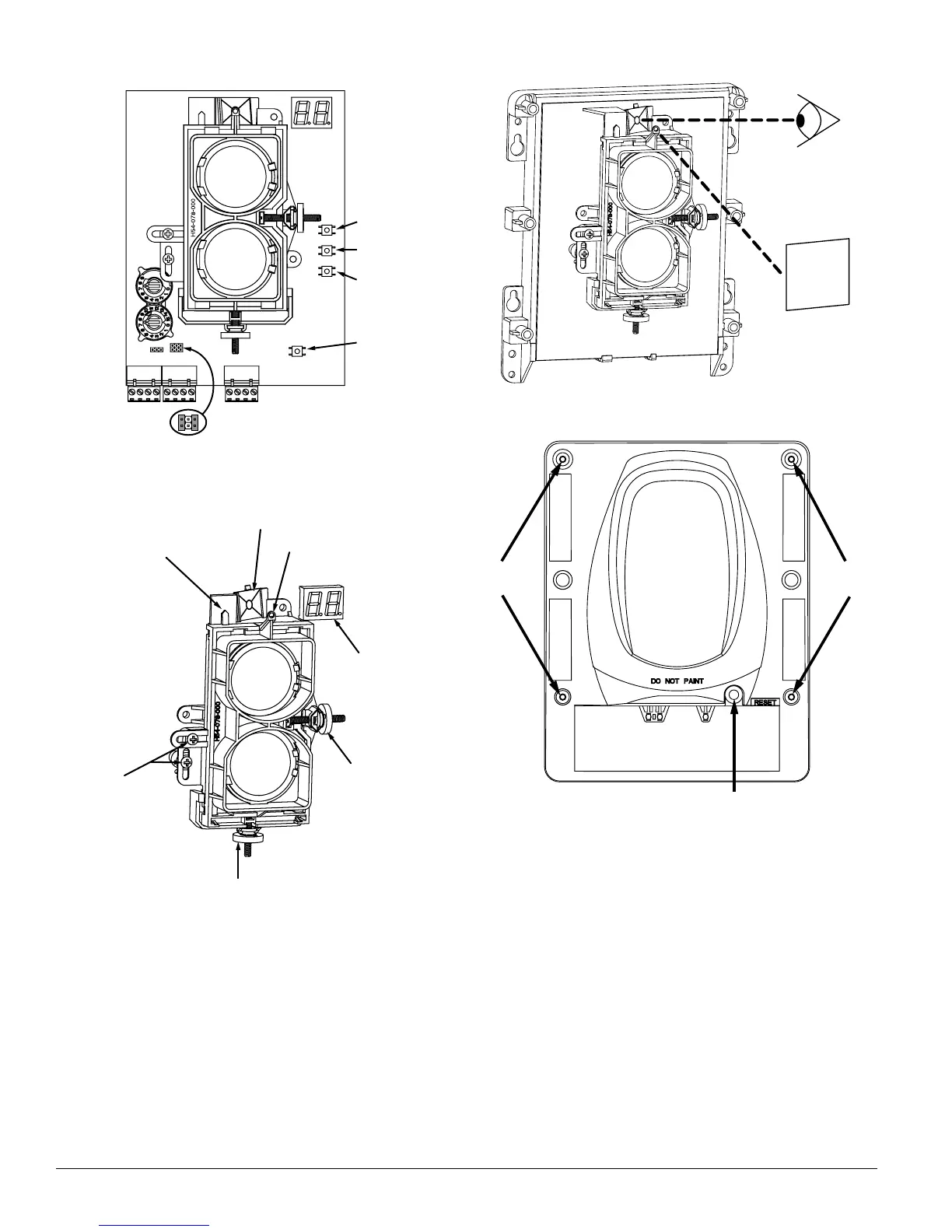
Figure 10. Switch Locations
ALIGNMENT
SENSITIVITY
TEST
RESET
STYLE 7 ISOLATOR SHUNTS
(SHOWN DISABLED)
CODE SWITCH
TENS
ONES
C0263-00
Figure 11. Alignment Adjustment Locations
ALIGNMENT MIRROR
ALIGNMENT GUNSIGHT
DIGITAL SIGNAL
STRENGTH
READOUT
HORIZONTAL
ADJUSTMENT
VERTICAL
ADJUSTMENT
OPTICS
LOCK-DOWN
SCREWS
ALIGNMENT
POSITION
INDICATOR
C0264-00
Figure 12. Coarse Alignment Procedure
C0265-00
Figure 13. Housing Screw Locations
SCREW
LOCATIONS
SCREW
LOCATIONS
RESET
SWITCH
C0266-00
Short Circuit Isolation
The detector includes an on-board circuit isolator that
allows for NFPA72 style 7 operation. In cases where style 7
operation is not desired the isolator can be disabled using
the two shunts on the circuit board. See Figure 10 for jump-
er locations. When the jumpers are present the isolator is
disabled. This is the default state.
Sensitivity Selection
The detector has six sensitivity selections. Each of these
selections is only acceptable over a specific distance sepa-
ration between the detector and the reflector per UL268.
The chart below is used to determine which selections are
N200-25-00 10 I56-2424-04R