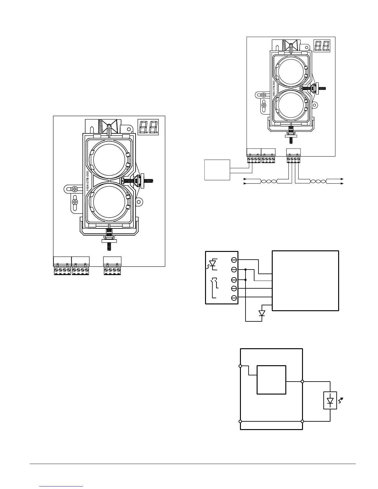
remote test stations (RTS451 or RTS451KEY). Figure 9
shows the remote output for alarm indication.
WARNING: Disable the zone or system before applying
power to the beam detector to prevent unwant-
ed alarms. When applying power to the beam
detector before the alignment procedure has
been completed the detector may enter alarm
or fault.
Figure 6. Wiring Connections at Detector
SLC (–)
SLC (+)
SLC (–)
SLC (+)
RESET I NPUT
TEST INPUT
AUX (–)
REMOTE ALARM OUT
Not used
REMOTE TROUBLE OUT
TEST OPTION (–)
TEST OPTION (+)
T3 T2 T1
C0260-01
Figure 7. Wiring Diagram
+ –
+ –
+
+
TO NEXT
DEVICE
FROM PANEL OR
PREVIOUS DEVICE
LISTED
REMOTE
POWER
SOURCE
* Only used for
FSB-200S. See
electrical ratings.
COMMUNICATION LINE
32 VDC MAX.
TWISTED PAIR IS
RECOMMENDED.
–
–
–
+
T3 T2 T1
C0335-00
Figure 8. Wiring Diagram (RTS451)
RTS451/KEY
FSB-200/FSB-200S
Pin 1
Remote Alarm Out
T2-1
T2-2
T2-4
T2-3
AUX (–)
Power In +T1-1
T1-2
T1-3
T1-4Power In –
Power Out +
Power Out –
Reset Input
Test Input
T3-3
Remote Trouble Output
Optional Yellow LED
Pin 2
Pin 4
Pin 3
Pin 5
C0336-01
Figure 9. Wiring Diagram (RTS451)
FSB-200S
Alarm
Signal
Circuit
(Note 1)
T2-1
T2-2
Note 1: See electrical ratings section of this
manual for circuit output ratings.
SLC (+)
SLC (–)
Red
C0326-00
N200-25-00 7 I56-2424-04R