N770-05-00 3 I56-480-03
Field Wiring
WARNING
High Voltage. Electrocution Hazard. Do not handle live AC
wiring or work on a device to which AC power is applied.
Doing so may result in severe injury or death.
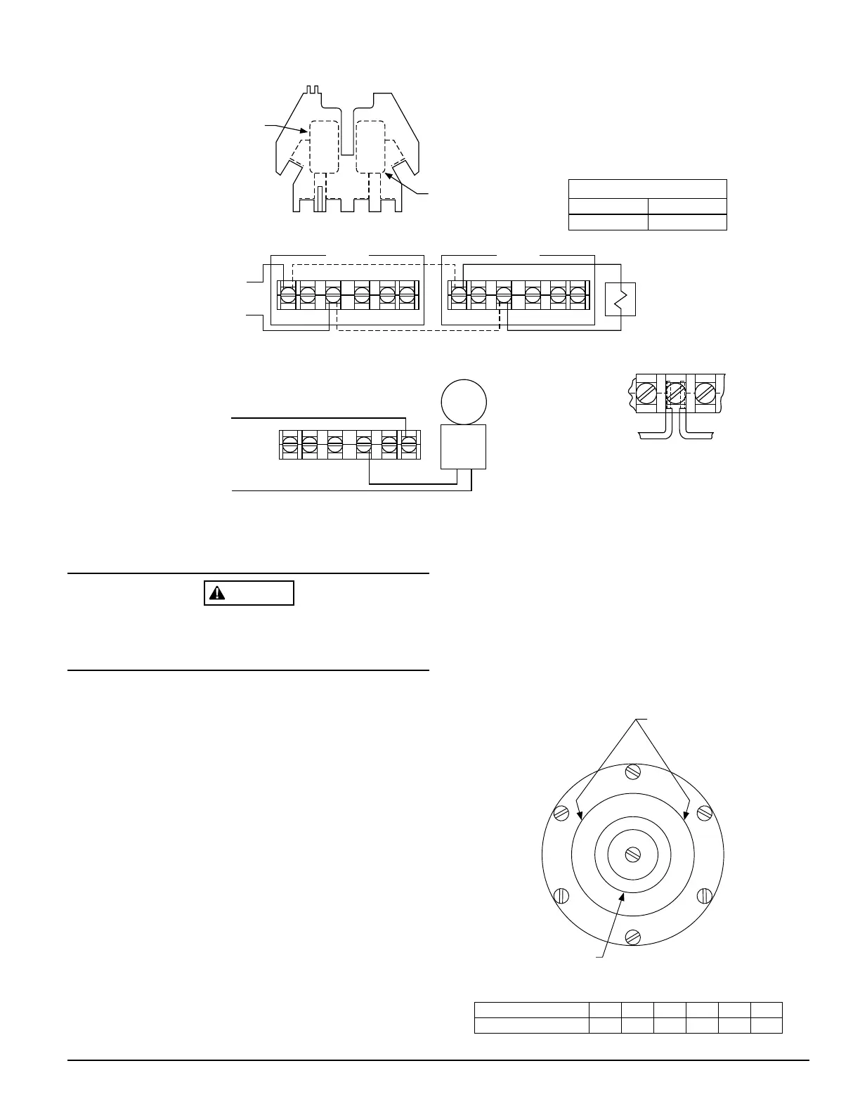
1. The WFDT and WFDTH have two SPDT switches. Switch
contacts (COM and B) are closed when water is flowing
and open when water is not flowing. Connect the switches
as shown in Figure 3 depending on the application.
2. When connected to a listed sprinkler/fire alarm control
panel, the initiating circuit must be non-silenceable.
3. A ground screw is provided with all units. When ground-
ing is required, clamp wire with screw in hole located
between conduit entrance holes. See Figure 2.
Mechanical Delay Adjustment
The pneumatic delay is preset at dial setting 2 at the
factory. To adjust the delay, turn the adjustment dial on the
delay mechanism. Turn clockwise to increase the delay,
counterclockwise to decrease the delay. Delay can be
adjusted over a range from 0-70 seconds. See Figure 4.
NOTE: Set the delay to the minimum required to prevent
false alarms due to flow surges.
After extended service, parts of the detector may become
worn reducing the delay time and causing false alarms. If
this happens, increase the delay. If the delay is already at
maximum, replace the mechanical delay assembly. Refer to
Maintenance section for ordering replacement parts.
Figure 3. Field wiring:
Top View
Switch 1
COM
COM
ABB A
Switch 2
NOTE: Common and B connections will
close when vane is deflected, i.e.,
when water is flowing. Dual switches
permit applications to be combined
on a single detector.
CONTACT RATINGS
125/250 VAC
24 VDC
10 AMPS
2.5 AMPS
WFDTH
WFDT
BB
COM COM
WFDTH
WFDT
BB
COM COM
Typical FACP Connection
to nonsilenceable initiating
zone of listed FACP
end-of-line resistor
B
COM
to power source
compatible
with bell
local
bell
WFDT and WFDTH
switch assembly
Typical Local Bell Connection
Break wire as shown for
supervision of connection.
DO NOT allow stripped wire
leads to extend beyond
switch housing. DO NOT
loop wires.
A78-1992-00
Figure 4. Delay adjustment dial:
0
3
4
5
1
2
2
1
0
3
4
5
45
55
70
30
15
0
Table of dial settings
embossed here.
See below.
Delay adjustment dial
0
0
1
15
2
30
3
45
4
55
5
70
Dial setting
Seconds (±50%)
A78-1596-05
Technical Manuals Online! - http://www.tech-man.com