N770-03-00 3 I56-394-05
nipple, orienting the PIBV2 to trip the switch as the
valve closes. If the conduit entry is on the wrong side, it
will be necessary to reverse the action of the switch (see
Section 4). Apply pressure to PIBV2 and tighten set
screws to secure the assembly.
7. Slide the actuating arm into the valve until it bottoms on
the flag, but do not tighten set screw.
8. Open the valve to the full open position and tighten set
screw to hold actuating arm in position. (Actuating arm
length will adjust slightly as valve is opened.) Check to
ensure that in the full open position the actuating arm is
not resting on the nipple. Do this by depressing the actu-
ating cam to further stretch the spring, ensuring that
more travel is available when the valve is open. If there
is no travel, damage may occur to PIBV2 actuating arm.
Some slight alteration of the valve stop setting may be
necessary to ensure that no damage occurs.
9. Carefully close valve and note the number of handle
revolutions until the switch trips. The switch must trip
within
1
/5 of the total travel range of the valve.
Section 3
General Installation Instructions
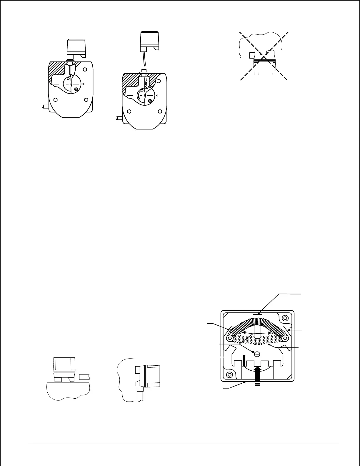
1. Installation Positions
Figure 4:
The following are examples of acceptable mounting
positions:
Actuator Vertical (Down) Actuator Horizontal
The following mounting position is not acceptable:
T
O
O
P
E
N
CLOSE
CLOSE
Figure 3:
Conduit Entry
Phillips
Screw
Spring
in final
position
Actuating Lever
Switch Enclosure
Spring
in initial
position
Slide in
this direction
Figure 5:
A78-1631-00
Actuator Vertical (Pointing Up)
2. Ground Screw — A ground screw is provided with all
supervisory switch models. When grounding is required,
clamp wire with the screw in hole located near conduit
entrance.
3. Wiring — See Figure 6, Page 4.
Section 4
Reversing The Action Of Pibv2
1. Loosen the 3 phillips screws on the top of the black
switch enclosure so that the switch enclosure is loose
and free to move (see Figure 5).
2. Slide the switch enclosure away from the conduit entry
toward the actuating pivot arm as far as possible and
tighten the 3 screws to secure the enclosure. (Ensure
that switch enclosure remains oriented away from the
conduit entry as screws are tightened.)
3. Grasp the spring at the center and lift it over the actuat-
ing cam so that it seats on the opposite side of the actua-
tor (see Figure 5).
A78-1633-00
Technical Manuals Online! - http://www.tech-man.com