N770-06-00 3 I56-509-01
3. A ground screw is provided with all WFDT units. When
grounding is required, clamp wire with screw in hole lo-
cated between conduit entrance holes. See Figure 2.
WARNING
High Voltage. Electrocution Hazard. Do not handle live AC
wiring or work on a device to which AC power is applied.
Doing so may result in severe injury or death.
Maintenance
To prevent accidental water damage, control valves should
be shut tightly and the system completely drained before
waterflow detectors are removed or replaced.
Inspect detectors monthly for leaks. Test detectors at least
monthly as described under Operational Testing to insure
proper operation. This device is not designed for use on
“dry pipe” systems. Test more often if required by the au-
thority having jurisdiction.
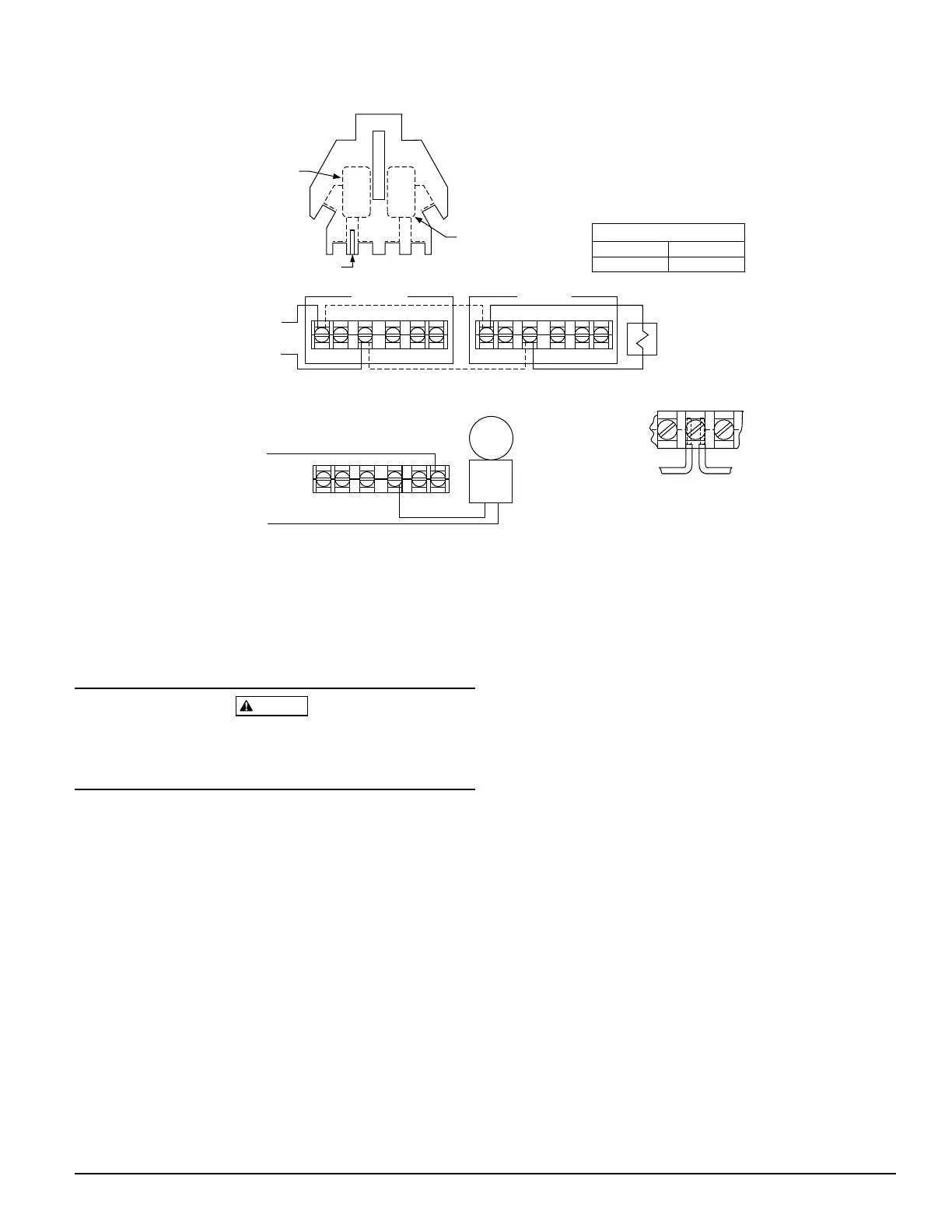
Figure 3. Field wiring:
Strip Gauge
Switch 1
COM
COM
ABBA
Switch 2
NOTE: Common and B connections will
close when vane is deflected, i.e.,
when water is flowing. Dual switches
permit applications to be combined
on a single detector.
CONTACT RATINGS
125/250 VAC
24 VDC
10 AMPS
2.5 AMPS
WFDTNR
BB
COM COM
WFDTNR
BB
COM COM
Typical FACP Connection
to nonsilenceable initiating
zone of listed FACP
end-of-line resistor
B
COM
to power source
compatible
with bell
local
bell
Typical Local Bell Connection
Break wire as shown for
supervision of connection.
DO NOT allow stripped wire
leads to extend beyond
switch housing. DO NOT
loop wires.
Under normal conditions System Sensor waterflow detec-
tors should provide years of trouble-free service. If, how-
ever, the switch enclosure becomes faulty, request Part No.
A77-01-08. If damage occurs to paddle, order replacement
kit PRK9. Refer to procedure below for removal of detector
on pipe. Do not repair or replace any other waterflow de-
tector components in the field. If any other part of the de-
tector does not perform properly, replace the entire
detector. Failure to follow this instruction may result in
failure of the detector to report a waterflow condition.
Proceed as follows to remove a detector:
1. Drain the pipe
2. Turn off electrical power to the detector, and then dis-
connect wiring
3. Unscrew WFDTNR from tee fitting
Technical Manuals Online! - http://www.tech-man.com