6.2.2 Assembly
WARNING
Danger from falling parts!
› Check the underground (ceiling/wall) for strength before assembly,
› when selecting the tting material, pay attention to the weight, vibration tendency and shearing
forces (weight, see name plate).
" Fit the fan on a rm base with suitable tting material at all the tting points.
" Secure the screw connections with Loctite.
" Fit the air channels and the accessories.
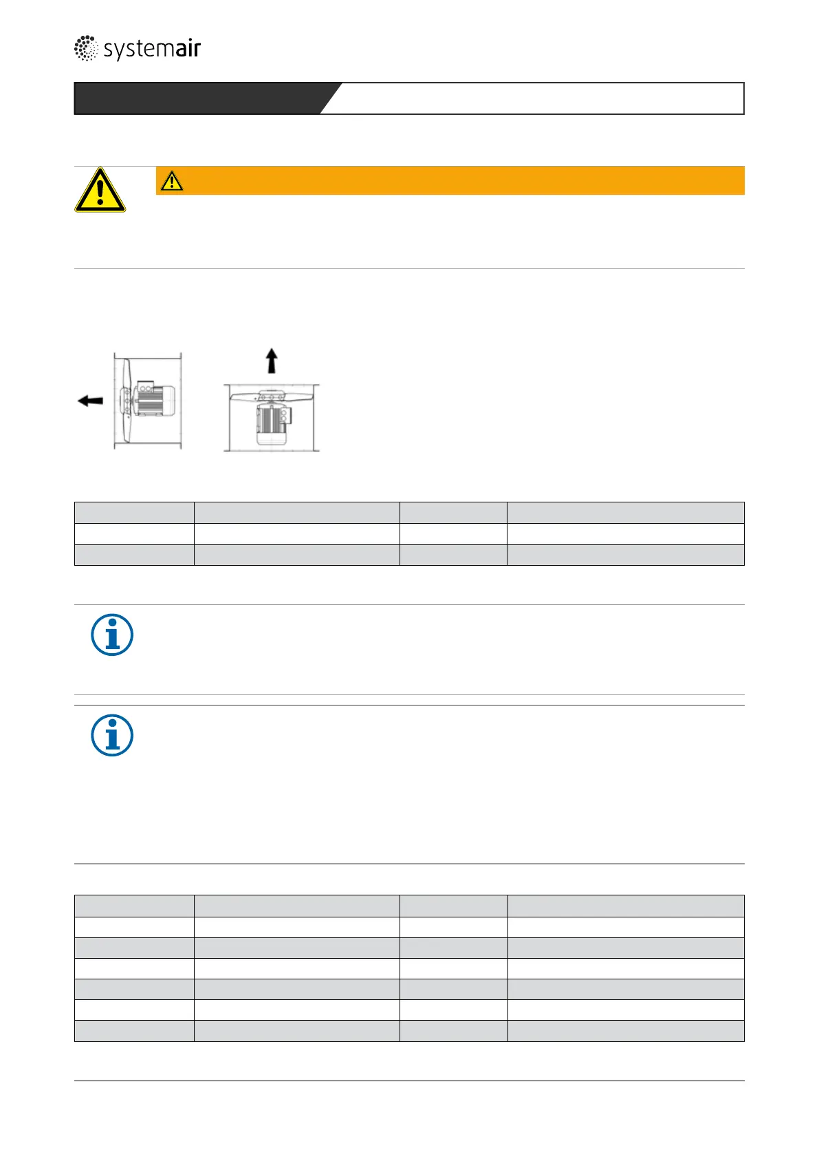
" Mounting AXC-EX and AXCBF-EX in horizontal and vertical ( impeller up) position possible!
6.2.3 AW-EX series: minimum air gap
Size Minimum air gap in mm Size Minimum air gap in mm
355 3,50 550 5,50
420 4,20 650 6,45
Table 10: Minimum air gap of various construction sizes
NOTE on the condensation opening of the AW-EX series
Pay attention in installation:
- In installation in a vertical motor shaft position, condensation cannot escape.
- Installation and operation only admissible in a horizontal shaft position
NOTE for an optimised characteristic
To ensure achievement of the characteristic, it is necessary for a constant and twist-free ow to exist at
the inlet. In free intake, this is achieved by the addition of an admission nozzle or a channel line with a
length of no less than 2.5 x D. If this is not possible for construction reasons, a deection piece with
bafes tted in front of the fan must be optimised in its uidics in such a way that a constant speed
distribution at the fan inlet is achieved.
On the pressure side, a channel or duct element with a length of no less than 2.5 x D is also to be
provided for achievement of the characteristic.
6.2.4 AXC-EX und AXCBF-EX series: minimum air gap
Size Minimum air gap in mm Size Minimum air gap in mm
250 2,5 710 5,0
315 2,5 800 5,0
355/400 3,0 900/1000 7,0
450/500 3,5 1250 8,0
560 3,5 1400/1600 10,0
630 4,5
Table 11: Minimum air gap of various construction sizes
56
 Loading...