6 Assembly
NOTE
The safety information in Section 6 applies to all the fans described in these operating instructions.
6.1 Safety information
Keep to the following order in order to rule out the risk of injuries from rotating parts:
Assemble
Connect to energy
HAZARD
Hazard of explosion of an ignition-capable atmosphere!
On the intake side, a protective grid has been attached in order to rule out the risk from foreign bodies.
It guarantees a protection class of IP20.
On the pressure side, protection class IP 20 must be guaranteed by assembly of the fan in a duct/
channel system or by tting a protective grid.
• Seal the system carefully.
• Install accessory parts correctly.
Upstream or downstream components or those located directly in the air ow may not manifest any
unprotected aluminium or steel surfaces. Varnishing or a plastic coating fullling at least grid section
characteristic 2 according to DIN EN ISO 2409 is necessary, in order to prevent an alumino-thermal
reaction.
• Assembly may only be done by trained qualied personnel paying attention to the relevant directives.
• Comply with the system-related conditions and the requirements of the system manufacturer or plant builder.
• Only install the fan when and if
– the fan has not been damaged,
– the fan wheel runs freely when turned by hand.
• The fan housing may not be deformed during assembly.
• Safety components, e.g. protective grids, may not be dismantled or circumvented or put out of function.
• Install the fan with protection against dust, moisture and the inuences of the weather.
• Do not distort the fan housing in installation. Surfaces must be at.
• Pay attention to the direction of ow (arrows).
• For maintenance and repair, ensure secure access to the fan.
• Provide for contact, intake protection and safety distances according to DIN EN 294 and DIN 24167-1.
• Ensure uninhibited and even admission into the device and free blow-out.
• In EX fans, the blade angle may not be amended subsequently.
• In installation, guarantee that no vibrations are transferred to the duct/channel system or the housing frame of the
fan in operation. For this purpose, use connecting sleeves and anges from the accessories.
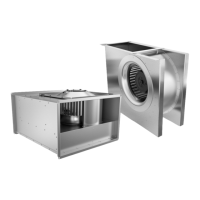
6.2 Axial fans AW-EX, AXC-EX and AXCBF-EX
6.2.1 Preconditions
AW-EX Only install the fan if the distance between the fan wheel and the housing is constant.
AXC-EX and
AXCBF-EX
Only install the fan if the minimum air gap between the blade tip and the housing matches the
value of your fan in Table 11.
55
Ex-fans - 10.2014
 Loading...