23
English
6 - Control
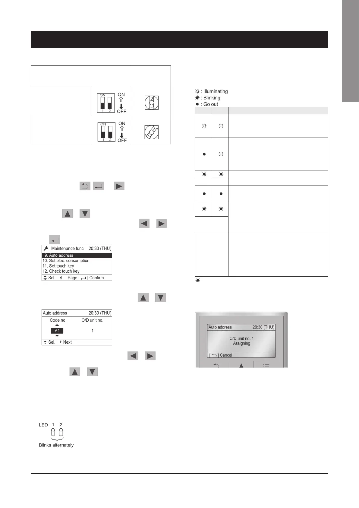
System address No.
System address
10s digit
(2P DIP switch)
System address
1s place
(Rotary switch)
0 Automatic address
(Setting at shipment = “0”)
Both OFF
“0” setting
1 (If outdoor unit is No. 1)
Both OFF
“1” setting
Automatic address setting using the remote controller
Auto Address Setting from the High-spec Wired Remote Controller
(CZ-RTC5B)
1. Keep pressing the , and buttons
simultaneously for 4 or more seconds. the "maintenance func"
screen appears on the LCD display.
2. Press the or button to see each menu. If you
wish to see the next screen instantly, press the or
button. Select "9. Auto address" on the LCD display and press
the button.
3. The "Auto address" screen appears on the LCD display.
Change the "Code no." to "A1" by pressing the or
button.
4. Select the “O/D unit no.” by pressing the or
button. Select one of the “O/D unit no.” for auto address by
pressing the or button. Approximately about 10
minutes are required. When auto address setting is completed,
the units return to normal stopped status.
Display During Auto Address Setting
n
On the surface of outdoor unit control P.C. board
Do not short circuit the A.ADD pin again during auto address
setting. LEDs 1 and 2 go out and address setting is interrupted.
When auto address setting is normally completed, both LEDs
1 and 2 go out. In other cases, correct settings referring to the
following table and perform auto address setting again.
n
Contents of LEDs 1 and 2 on outdoor unit control P.C. board
LED 1 LED 2 Contents of display
After turned ON power (not during auto address
setting), it is entirely impossible to communicate with
the indoor unit in the system.
After turned ON power (not during auto address
setting), although the indoor units more than 1 unit
in the system are recognized, there are inconsisten-
cies between the number of indoor units and setting
number of indoor units.
Under auto address setting
Alternately
Auto address setting completed
There are inconsistencies between the number of
indoor units and setting number of indoor units. (at
the time of auto address setting)
Simultaneously
Alternating
After LED1 blinks M times, LED2 blinks N times.
This will be repeated:
• 2 Blinks - Alarm P
• 3 Blinks - Alarm H
• 4 Blinks - Alarm E
• 5 Blinks - Alarm F
• 6 Blinks - Alarm L
Blink: Connect the outdoor unit maintenance remote
controller to the RC plug (3P, BLU) on outdoor main unit control
P.C. board and make confirmation.
n
Display of remote controller
Request concerning recording the indoor/outdoor unit
combination numbers.
After auto address setting has been completed, be sure to
record them for future reference.
List the outdoor main unit system address and the addresses of
the indoor units in that system in an easily visible location (next
to the nameplate), using a permanent marker pen or similar
means, that cannot be abraded easily.
 Loading...