EasyManua.ls Logo

SystemAir SAVE–P VTR 150/B - User Manual

SystemAir SAVE–P VTR 150/B
26 pages
Print Icon
To Next Page IconTo Next Page
Loading...
Document in original language | 271401 · v1
SAVE–P VTR 150/B
Installation instructions
GB
Question and Answer IconNeed help?

Do you have a question about the SystemAir SAVE–P VTR 150/B and is the answer not in the manual?

Summary

1 Overview

1.1 General Description

Provides a general overview and references for advanced settings and accessories.

1.2 Warranty

Details prerequisites for warranty claims: correct connection, operation, maintenance, and commissioning.

1.3 Type label

Explains the information found on the product's type label, including product code and serial number.

2 Important Safety Information

2.1 Intended Use

Specifies device usage according to system requirements and the need for legible warning signs.

2.2 Admonitions

Lists crucial safety warnings for electrical work, supervision, sharp edges, and rotating parts.

3 Technical Data

3.1 Dimensions and Weight

Presents detailed physical dimensions and weight of the unit, including diagrams for clarity.

3.2 Connections Left and Right models

Illustrates the left and right handed connection configurations for the unit's air ducts.

3.3 Installation recommendation regarding condensation

Provides guidance on preventing condensation inside and outside the unit based on conditions.

3.3.1 Condensation inside of the unit

Explains how to prevent internal condensation during shutdown periods using dampers.

3.3.2 Condensation outside of the unit

Details factors causing external condensation and provides a chart for reference.

4 Delivery, Transport, Storage

4.1 Transport and storage

Outlines proper methods for storing and transporting the unit to prevent physical damage.

4.2 Delivery;Unloading

Describes the unit's delivery condition and emphasizes careful handling during unloading.

5 Prerequisites for Installation

5.1 Location and Space Requirements

Defines necessary placement and spatial clearances for mounting the unit above a stove.

5.2 Wall preparation for mounting bracket

Provides instructions for preparing the wall surface for stable, vibration-free mounting.

5.3 Outdoor Air Intake Location Recommendation

Recommends optimal locations for outdoor air intake to avoid pollution sources.

5.4 Access to Power supply

Specifies power supply requirements and the location of the unit's power cable and plug.

6 Installation

6.1 Wall preparation for mounting bracket

Details the preparation of the mounting surface, ensuring it is flat, vertical, and can support the unit's weight.

6.2 Installation with 251-10;B cooker hood

Guides the installation process when pairing the unit with a 251-10/B model cooker hood.

6.3 Installation with 392-10;B cooker hood

Provides instructions for installing the unit with a 392-10/B model cooker hood, including mounting options.

6.3.1 Installation between or in a cupboard without a base with a cooker hood attached directly to the unit

Details attaching the cooker hood directly to the unit in a cupboard without a base.

6.3.2 Installation between or in a cupboard without a base using brackets

Explains using brackets for cooker hood installation in a cupboard without a base.

6.3.3 Optional installation in a cupboard with a base

Describes an optional installation method for fitting the unit into a cupboard with a base.

6.4 Wiring and configuration

Covers the electrical wiring and configuration steps for the cooker hood function on the main circuit board.

6.5 Installation of a kitchen furniture panel

Explains mounting a kitchen furniture panel to the unit, cabinets, or as a door.

6.5.1 Mounting the kitchen furniture panel directly on the unit

Details directly mounting a kitchen furniture panel onto the unit, with adjustments for cupboard depth.

6.5.2 Mounting the kitchen furniture panel on sides of cabinets

Describes installing a kitchen furniture panel onto cabinet sides using included brackets.

6.5.3 Fitting the kitchen furniture panel as a door

Suggests using hinges to fit the kitchen furniture panel as a hinged cupboard door.

7 Electrical connections

7.1 Main circuit board layout

Illustrates the layout and components of the unit's main circuit board for electrical connections.

8 Before Starting the System

9 Commissioning

10 Concluding Routines

11 Disposal and recycling

12 EU Declaration of Conformity

Overview

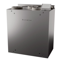
The Systemair SAVE-P VTR 150/B is a ventilation unit designed for residential applications, specifically intended for installation above a stove. It is an air handling unit that facilitates both supply and extract air, incorporating a cooker hood function. The unit is designed to operate continuously, with provisions for maintenance and service.

Function Description

The SAVE-P VTR 150/B is an air handling unit that manages the ventilation in a residential space. It provides supply air to the building and extracts stale air, including air from a cooker hood. The unit is equipped with a re-heater, fans, and various sensors to monitor and control air quality and temperature. It is designed to prevent condensation both inside and outside the unit, especially when installed in cold attics or warm, humid areas. The unit's operation can be configured through a startup wizard, allowing for adjustments to airflow levels, heating type, and filter change timers. It can be integrated with a cooker hood, either directly attached to the unit or connected via a flexible duct, to efficiently remove cooking fumes.

Important Technical Specifications

  • Product Code: SAVE-P VTR 150/B
  • Power Supply: 230V~, single phase earthed connection, 50/60Hz
  • Total Power Consumption: 1172 W (Re-heater: 1000 W, Fans: 172 W)
  • Fuse: 10 A
  • Dimensions (Left Hand Model):
    • Width: 596 mm
    • Height: 630 mm
    • Depth: 368 mm
  • Weight: 46 kg
  • Duct Connections: Ø 125 mm x 5
  • Models: Available in Left Hand (supply air connection on the left) and Right Hand (supply air connection on the right) configurations.
  • Minimum Distance between Cabinets: 600 mm
  • Unit Width: 596 mm
  • Minimum Distance between Stove Surface and Cooker Hood: 450 mm (recommended 500 mm) for electrical stoves, 650 mm for gas stoves.
  • Cooker Hood Height: 150 mm (for 251-10/B) or 97 mm (for 392-10/B)
  • Total Height (unit + cooker hood + 100 mm flexible duct): 790 mm (for 251-10/B) or 737 mm (for 392-10/B)
  • Distance to Mounting Bracket from Underside of Cooker Hood/Cupboard: 750 mm (for 251-10/B) or 697 mm (for 392-10/B)
  • Power Cable Length: Approximately 1.9 m
  • Protection Degree: IP24
  • Compliance: CE, UKCA, EAC marked. Complies with Machinery Directive 2006/42/EC, Ecodesign Directive 2009/125/EC, Low Voltage Directive 2014/35/EU, EMC Directive 2014/30/EU, RoHS Directive 2011/65/EU, 2015/863/EU, and various EN standards (ISO 12100, 13857, 60204-1, 60335-1, 60335-2-40, 50106, 60529, 62233, 61000-6-2, 61000-6-3, 13053, 13142).

Usage Features

  • Integrated Cooker Hood Function: The unit is specifically designed to work with Systemair cooker hoods (models 251-10/B and 392-10/B), allowing for direct attachment or connection via a flexible duct.
  • Condensation Management: Recommendations are provided to prevent condensation both inside and outside the unit, particularly for installations in cold attics or humid environments. Continuous operation is advised in cold attics, and air-tight dampers are recommended for ducts if the unit is stopped.
  • Adjustable Installation: The unit offers flexibility in installation depth, allowing for the use of wooden blocks to align with cupboard depths. Mounting brackets are adjustable to fit various cupboard depths.
  • Kitchen Furniture Panel Integration: The unit supports the installation of a kitchen furniture panel directly on the unit, on the sides of cabinets, or as a hinged door, allowing for seamless integration with kitchen aesthetics.
  • User-Friendly Configuration: A startup wizard guides the user through initial settings, including language, date/time, and airflow control type. Airflow levels for supply and extract fans can be set for maximum, high, and normal operation.
  • Safety Features: The unit includes warnings regarding sharp edges during mounting and maintenance, emphasizing the use of protective gloves. It also highlights the importance of disconnecting the mains supply before any electrical work and ensuring all work is carried out by authorized installers.
  • Continuous Operation: The system is designed for continuous operation, with stops only for maintenance or service.
  • Electrical Connections: The unit features a main circuit board with clearly labeled terminals for various connections, including heater, TRIAC, mains power, fan power, and sensors (humidity/temperature, outdoor air, supply air, overheat temperature). It also includes digital inputs for a rotor guard sensor and cooker hood function.

Maintenance Features

  • Removable Kitchen Furniture Panel: If a kitchen furniture panel is installed between cabinets, it must be removable to allow for regular maintenance of the unit.
  • Accessible Electrical Connection Box: The electrical connection box is located on the exhaust air outlet side of the unit, and the print card can be easily removed without special tools, facilitating electrical maintenance.
  • Filter Management: The startup wizard includes an option to reset the filter change timer, indicating that filter maintenance is a regular requirement. Filters must be mounted before starting the unit.
  • Commissioning Record: A commissioning record is to be filled out during startup and for any subsequent changes, ensuring a comprehensive history of the unit's configuration and maintenance.
  • Warranty Conditions: To assert warranty claims, the product must be correctly connected, operated according to data sheets, and have a completed maintenance plan and commissioning report.
  • Disposal and Recycling: The product is compliant with the European WEEE Directive, and its packing materials are recyclable. Instructions are provided for proper disposal and recycling according to local regulations.

SystemAir SAVE–P VTR 150/B Specifications

General IconGeneral
BrandSystemAir
ModelSAVE–P VTR 150/B
CategoryIndustrial Equipment
LanguageEnglish

Related product manuals