Installation |
13
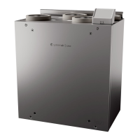
Fig. 14 Installation using brackets
2. Attach the brackets as far into the cooker hood as pos-
sible. Insert the cooker hood up into the hole in the
base of the cupboard. Pull out (figure 14, pos. A) and
use screws to fasten the brackets to the sides of the
cupboard (figure 14, pos. B). Tighten the brackets in
the cooker hood.
6.4 Wiring and configuration
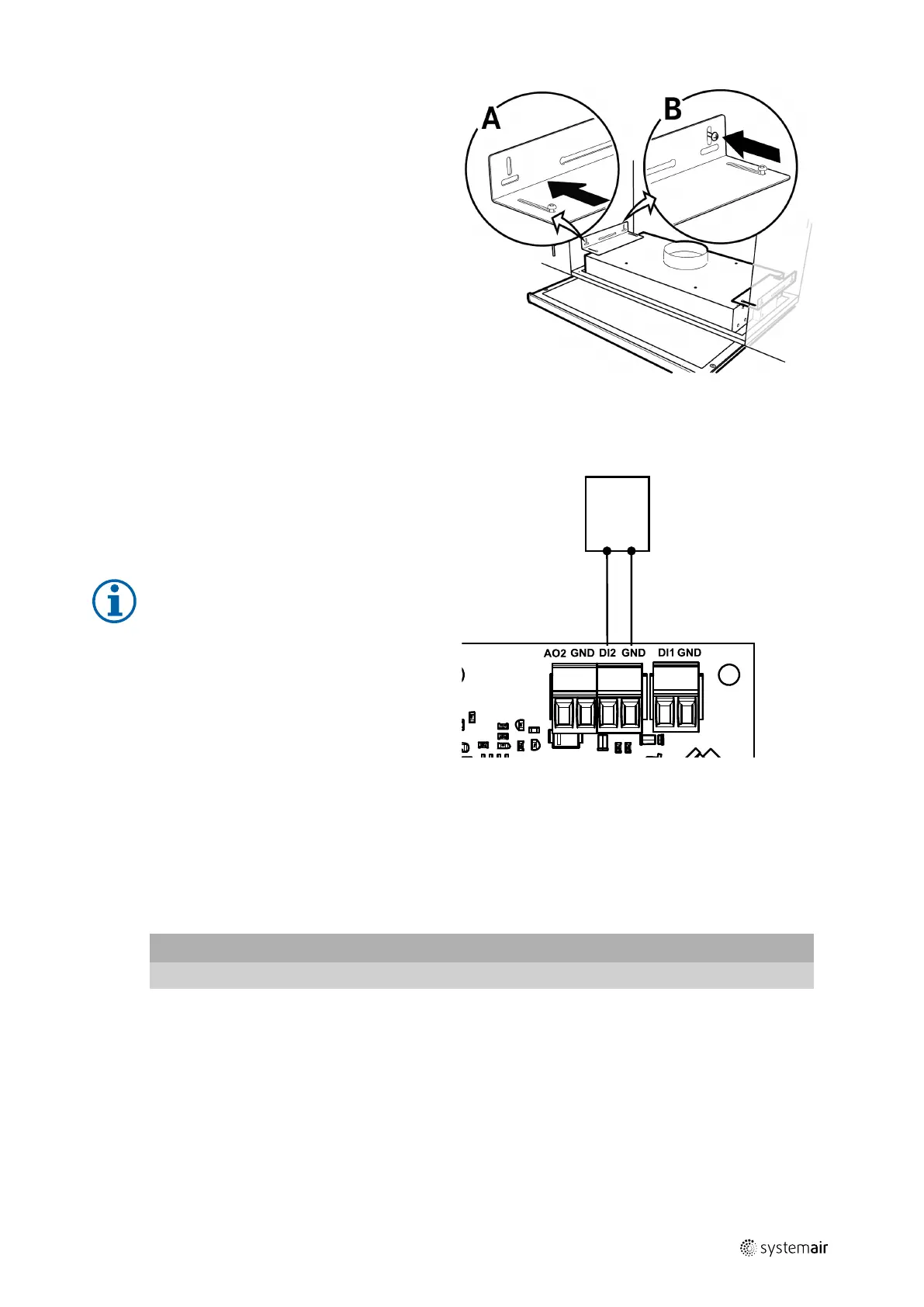
Fig. 15 Connection of the cooker hood
Installation and connection
1. Lead the cooker hood control wires through a rubber
grommet on top of the unit.
2. Connect wires to the digital input 2 (DI2) on the main
circuit board.
Note:
Configuration of the Cooker Hood Function
can be done only after the first power up of
the SAVE–P VTR 150/B unit and competed
startup wizard.
Configuration
1. Go to Service menu
2. Enter password (default 1111)
3. Go to Input menu. Select DIGITAL tab.
4. Select DIGITAL INPUT 2. Select an option Cooker Hood Function from the input type list.
Important
Make sure configuration is logged in the commissioning record!
6.5 Installation of a kitchen furniture panel
The kitchen furniture panel can be mounted directly on the unit, sides of cabinets or installed as a door. Parts for panel
installation directly on the unit and sides are delivered with the unit.
271401 | v1
 Loading...