12
| Installation
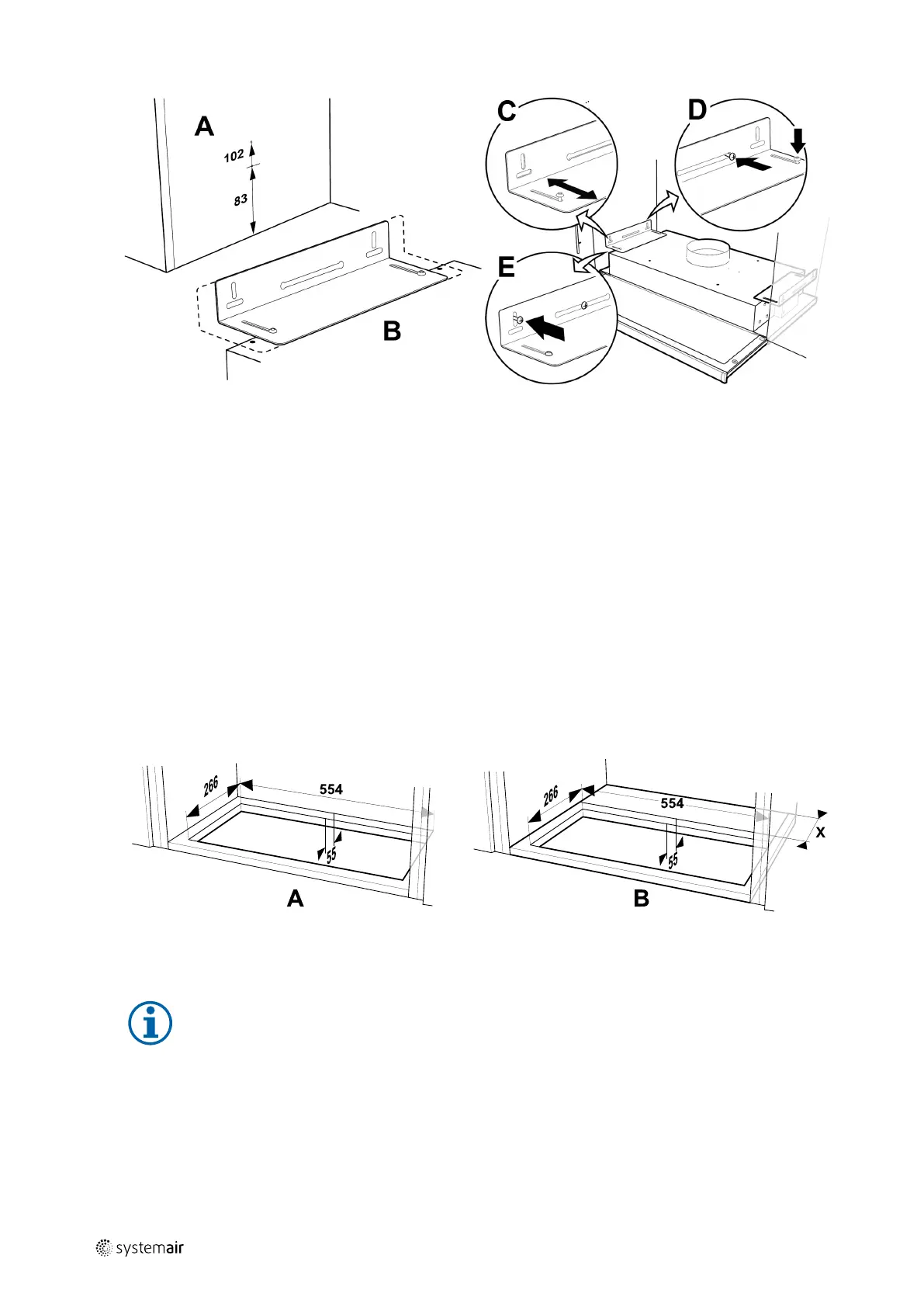
Fig. 12 Installation using brackets
Mark out and fasten screws so that they protrude a few millimetres from both cupboard sides (figure 12, pos. A). If it
is intended to align the underside of the cooker hood with the underside of the row of cupboards, use the upper
measurement 102; see figure 12, pos. A. The cooker hood brackets are adjustable to fit various cupboard depths (fig-
ure 12, pos. B).
2. Move the cooker hood brackets without fully tightening the screws and adjust the brackets so that they fit the sides
of the cupboards (figure 12, pos. C). Hang the cooker hood in the pre-installed screws in the side of the cupboard.
Tighten the screws in the bracket and on the wall (figure 12, pos. D). Lock the brackets into position using the locking
screws (figure 12, pos. E).
Mounting the unit with the cooker hood installed using brackets
1. Pull the cooker hood power supply and control cables to the top since the mounted SAVE–P VTR 150/B unit will block
access to the back.
2. Once all cooker hood cables at the back are led to the top, lift the unit and hang it on the mounting bracket.
3. Connect the cooker hood and the SAVE–P VTR 150/B unit using flexible duct.
6.3.3 Optional installation in a cupboard with a base
1.
Fig. 13 Dimensions of a hole in the base of the cupboard
Using a saw, cut out a hole in the base of the cupboard. When the SAVE–P VTR 150/B unit is mounted directly on the
wall, the minimum distance from the wall to the hole has to be 55 mm (figure 13, pos. A).
Note:
Be sure to add the thickness (dimension X) of your wooden blocks if they were used (figure 13, pos. B).
271401 | v1
 Loading...