Accessories
|
35
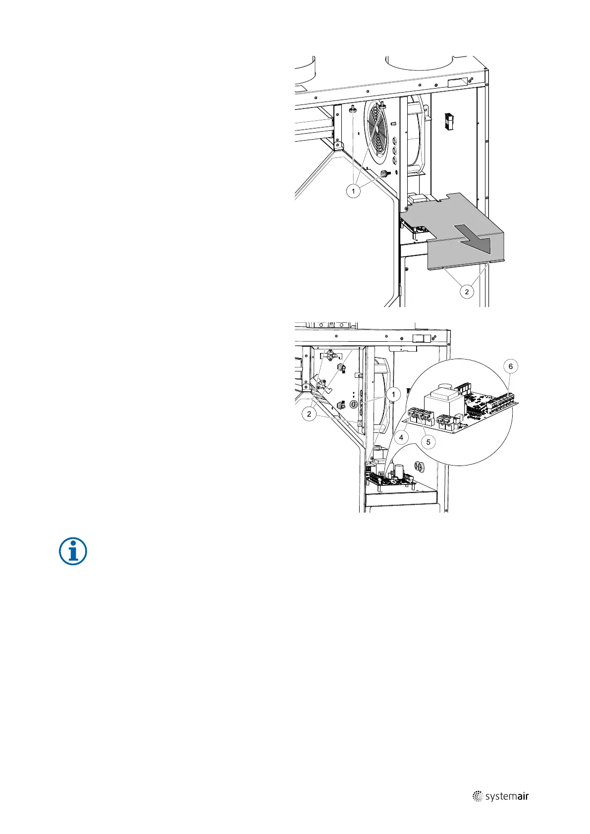
2 Remove knobs in the reheater compartment (pos. 1),
they will be used to hold the reheater in place.
Remove the main circuit board cover plate by remov-
ing 2 screws (pos. 2) in the lower front edge of the
plate.
3 Insert reheater, lead cables trough holes on the side
(pos. 1).
Secure reheater in place using previously removed
knobs (pos. 2).
• Connect reheater control wires to the terminal
block marked as HEATER (pos. 4) on the main cir-
cuit board. Connect blue wire to N socket, brown
wire to L socket.
• Connect TRIAC wires to the terminal block marked
as TRIAC (pos. 5) on the main circuit board. Connect
black wire to G socket, brown wire to A1 socket,
gray wire to A2 socket.
• Connect overheat protection sensor to any free
analog input on the main circuit board (pos. 6).
Connect black wire to ground (GND), red fire to
analog input.
4 Place back covers of reheater and the main circuit
board and secure them with screws.
Note:
For more detailed information see a wiring diagram delivered with the unit.
Configuration
1. Go to Service menu
2. Enter password (default 1111)
3. Go to Components menu, select Heater menu and select type as Electrical. Do advanced settings if necessary.
4. Configure overheat protection sensor. Go back to Input menu. Select ANALOG tab. Select the analog input to which
the overheat protection sensor is connected. Example if it is connected to AI4 on the main circuit board, then select
ANALOG INPUT 4 and select Overheat Temperature Sensor (OHT) from the input type list.
5. Configure TRIAC. Go to Output menu. Select ANALOG tab then select TRIAC OUTPUT and set output type as Y1
Heating.
211464 | A001

 Loading...