40
|
Accessories
Configuration
1. Go to Service menu
2. Enter password (default 1111)
3. Activate the actuator. Go to Components menu, select Cooler menu and select type as Water. Choose actuator
voltage type. Do advanced settings if necessary.
4. Configure connection of the duct cooler. Go to Service menu. Select Output menu. In next menu select ANALOG
tab. Select the analog output to which the water cooler is connected. Example if it is connected to AO3 on the con-
nection board, then select ANALOG OUTPUT 3 and select Y3 Cooling from the output type list.
5. Since a duct temperature sensor replaces internal supply air temperature sensor, it doesn’t need to be re-configured.
Note:
A duct temperature sensor can be connected to analog inputs 6–7 on the connection board for better
access when the internal supply air temperature sensor is disabled in the control panel. Then temperature
sensor has to be re-configured as universal analog input.
6. Duct cooler and its components are now configured.
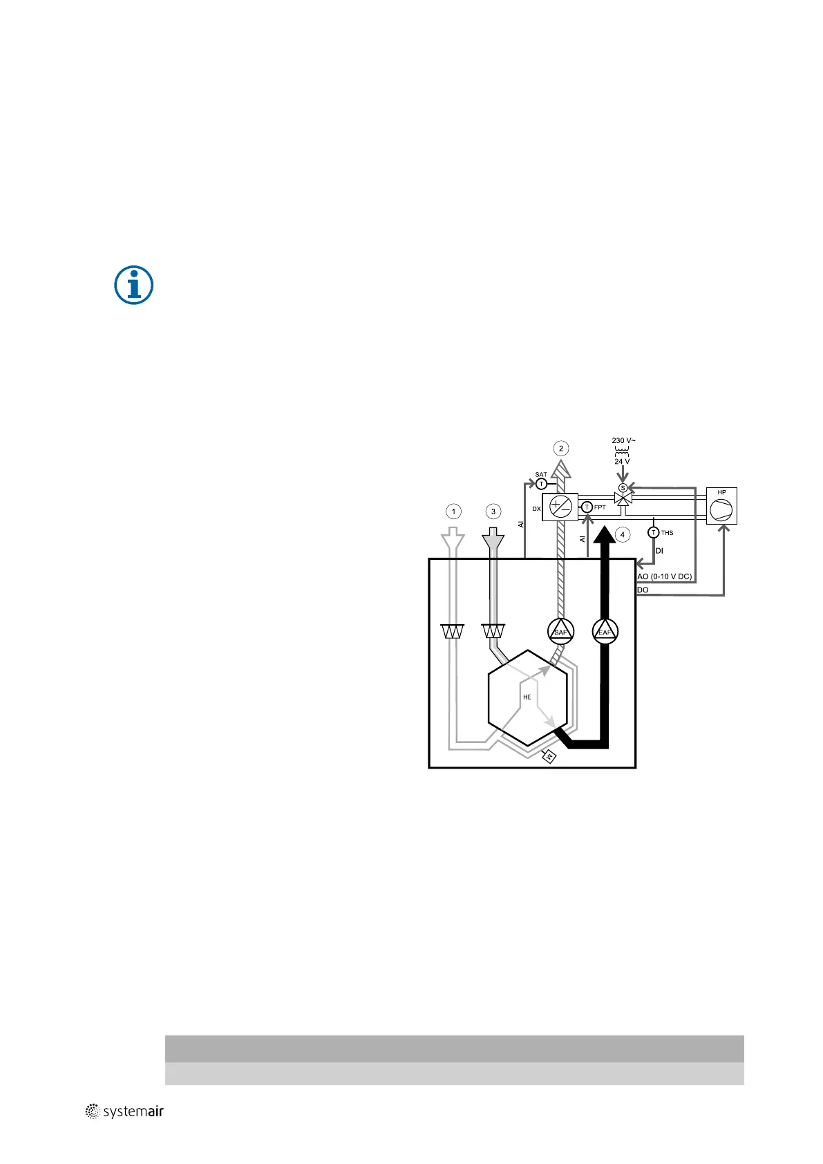
9.3.5 Change-over coil (DX)
Change-over (DX) coils can be used for both heating and cooling based on the demand.
• DX — change-over coil
• FPT — frost protection sensor (optional)
• SAT — supply air temperature sensor
• THS — thermostat for feedback from pipe if correct
temperature available for heating/cooling (optional)
• HP — heat pump (or other device for heating and
cooling)
• S — actuator for valve
• 1 — Outdoor air
• 2 — Supply air
• 3 — Extract air
• 4 — Exhaust air
Component/product — Article number:
• RVAZ4 24A Actuator 0-10V (S) — 9862
• ZTV 15-0,4 2-way valve — 9829
• ZTV 15-0,6 2-way valve — 6571
• ZTR 15-0,4 valve 3-way — 9670
• ZTR 15-0,6 valve 3-way — 6573
• Duct sensor -30-70C (SAT) — 211524
• Surface sensor -30-150C (FPT) — 211523
• PSS48 Transformer 24V — 204385
Installation and connection
1. Install water heater in the duct. Connect pipes, 2/3–way valve and actuator.
Important
Do NOT use 24V DC power output from the connection board for valve actuator.
211464 | A001

 Loading...