Installation |
5
4.4.1.1 Connections Right and Left Models
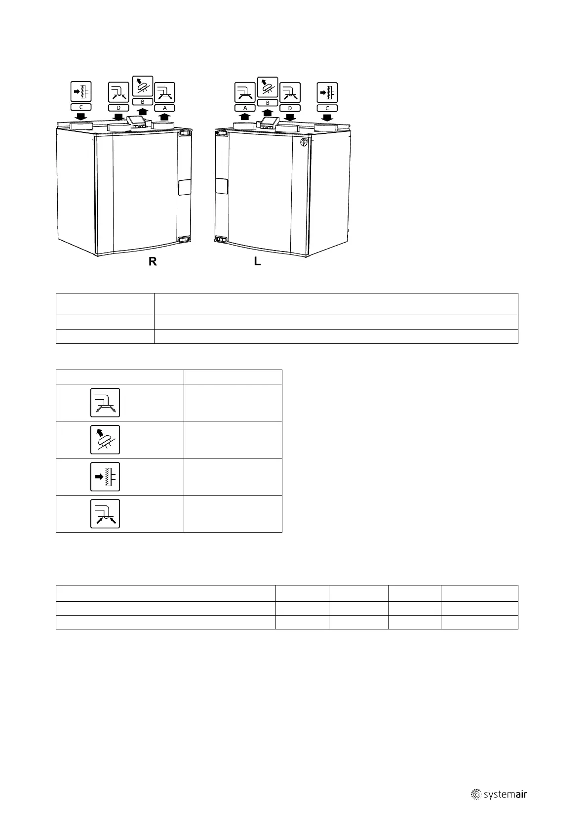
Fig. 2 Right and Left models
Position Description
R
Right hand model (Supply air connection and control panel is situated on the right hand side of the unit viewed from the front)
L
Left hand model (Supply air connection and control panel is situated on the left hand side of the unit viewed from the front)
Table 1 Symbol description
Symbol Description
A
Supply air
B Exhaust air
C Outdoor air
D Extract air
4.4.2 Power consumption and fuse size
Table 2 Power Consumption
Model
Fans (W ) Heater (W) Total (W) Fuse (mains) (A)
VTC 300 170
–
170 10
VTC 300 with reheater
170 1700 1870 10
5 Installation
This section describes how to install the unit correctly. To ensure a proper and fail free operation it is important that the
unit is installed according to these instructions.
5.1 Unpacking
Verify that all ordered equipment are delivered before starting the installation. Any discrepancies from the ordered
equipment must be reported to the supplier of Systemair products.
211464 | A001

 Loading...