Installation |
15
Fig. 9
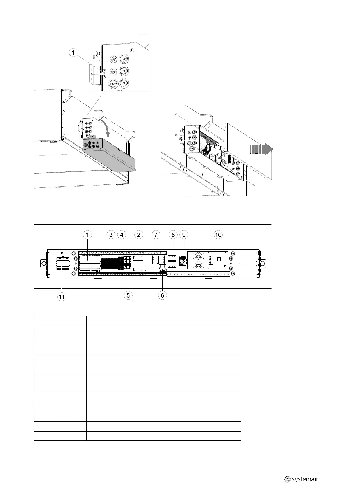
Topvex FC is equipped with a built in regulator and internal wiring (figure 10).
Fig. 10 Electrical components
Position
Description
1
Control unit CU283W-4
2
Transformer 230/24V AC
3
Terminals for internal and external components
4
Terminals for internal wiring
5
Terminals for power supply to the unit
6
Contactor (K2) On/Off Pump control water (HW units only, not
present in EL-units)
7
Automatic fuse
8
Automatic fuse for heater (EL units only)
9
Contactor (K3) EL heater (EL units only)
10
TTC El heater control (EL units only)
11
Switch module
151627 | A002

 Loading...