2.4InternalcomponentsElectricalconnectionbox
Danger
•MakesurethattheMainssupplytotheunitisdisconnectedbeforeperforminganymaintenanceor
electricalwork!
•Allelectricalconnectionsmustbecarriedoutbyanauthorizedinstallerandinaccordancewith
localrulesandregulations.
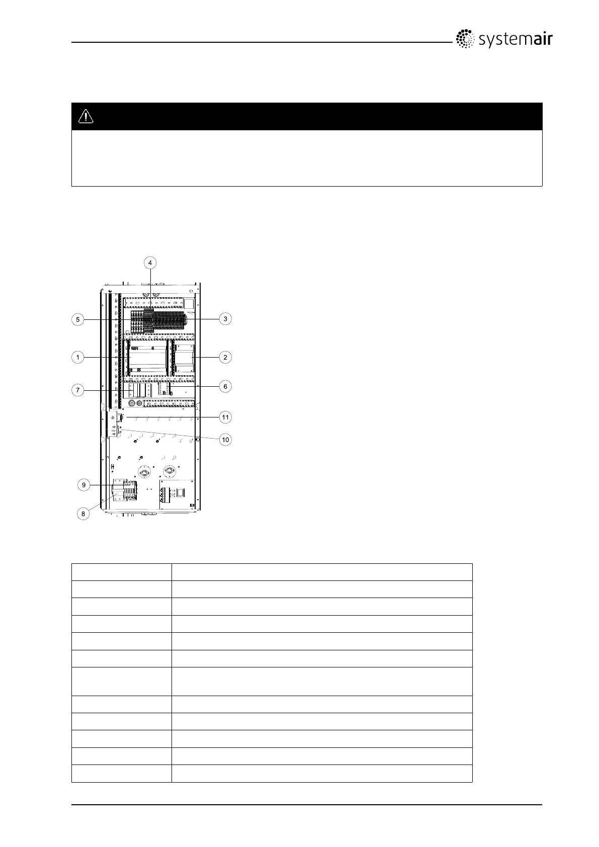
TopvexSR/TRareequippedwithabuiltinregulatorandinternalwiring(gure4).
ThegureshowstheelectricalconnectionboxfortheTopvexTR09-15units.Theconnectionboxfor
theSR09,SR11hasthesamelayoutandcomponentswiththedifferencethattheelectricalheateris
situatedinaseparatecompartment.
Fig.4Electriccomponents
Positiondescription
1RegulatorE-28
2
Transformer230/24VAC
3
Terminalsforinternalandexternalcomponents
4
Terminalsforinternalwiring
5
Terminalsformainssupplytotheunit
6
Contactor(K2)On/OffPumpcontrolwater(HWunitsonly,not
usedinEL-units)
7
Automaticfuse
8
AutomaticfuseforELheater
9
Contactor(K3)forcontrolofELheater
10
Thermostat(ELunits)
11
Manualoverheatprotectionreset(ELunits)
TopvexSR09,11,TR09-15OperationandMaintenanceInstructions
207880
6
SystemairAB

 Loading...