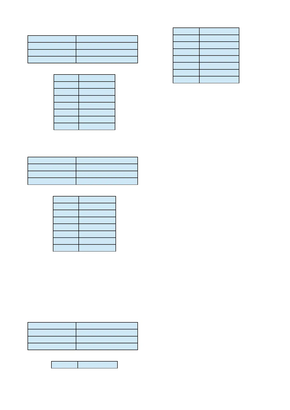
Manager Input Port
Type V.24/RS232 - Fixed DCE
Speed 9600bps (8,n,1)
Signals TXD, RXD, SIG GND
Connector 9-way Dsub Female
PIN SIGNAL
2 RXD (o/p)
3 TXD (i/p)
5 SIG GND
6 Relay 1 COM
7 Relay 1 N/O
8 GND
9 Opto 1 (i/p)
* Opto Input – Trigger by strapping to ground.
Manager Output Port
Type V.24/RS232 - Fixed DTE
Speed 9600bps (8,n,1)
Signals TXD, RXD, SIG GND
Connector 9-way Dsub Female
PIN SIGNAL
2 RXD (i/p)
3 TXD (o/p)
5 SIG GND
6 Relay 2 COM
7 Relay 2 N/O
8 GND
9 Opto 2 (i/p)
* Opto Input – Trigger by strapping to ground.
Auxiliary Data Port
The RS232 terminal interface can support auxiliary
bidirectional transmission of asynchronous data
over the ISDN and X21 network.
Type V.24/RS232 - Fixed DCE
Speed 9600bps (8,n,1)
Signals TXD, RXD, CTS, S GND
Connector 9-way Dsub Female
PIN SIGNAL
1 Alarm N/C
2 AUX RXD (o/p)
3 AUX TXD (i/p)
4 Alarm COM
5 SIG GND
6 Alarm N/O
8 AUX CTS (o/p)
9 Remote Trigger*
NOTE: The CTS output signal should be used for Flow
Control when Auxiliary Data is enabled.
Alarm Signal
The C510xr / C520xr provides a set of alarm relay
contacts with a minimum of 0.5 second duration.
These relay contacts are provided on the auxiliary
data port connector.
For connection information, please refer to the pin-
out detail of the auxiliary data connector. The
maximum voltage is 50V.
Remote Trigger
The Remote Trigger input operates by connecting
the Remote Trigger (Pin 9 of auxiliary data
connector) to GND and holding the connection. This
instructs the Codec to dial the ISDN using the
current selected patch configuration. To hangup the
ISDN call, disconnect the pin from GND.
The Remote Trigger can be Wire-Or connected for
multiple remote trigger access, e.g. several studios
sharing a single C510xr/C520xr unit.
Remote Trigger Input - Do Not Connect to Voltage
Outputs.
Page 20