M503 Series Wheelchair Scales Technical Manual
10.4. Check the Load cell
Remove power from the system, and disconnect the PCB from the Load
cell
Check the moisture, or foreign material inside.
Make sure all leads are connected and correctly.
Check load cell for proper input and output resistances
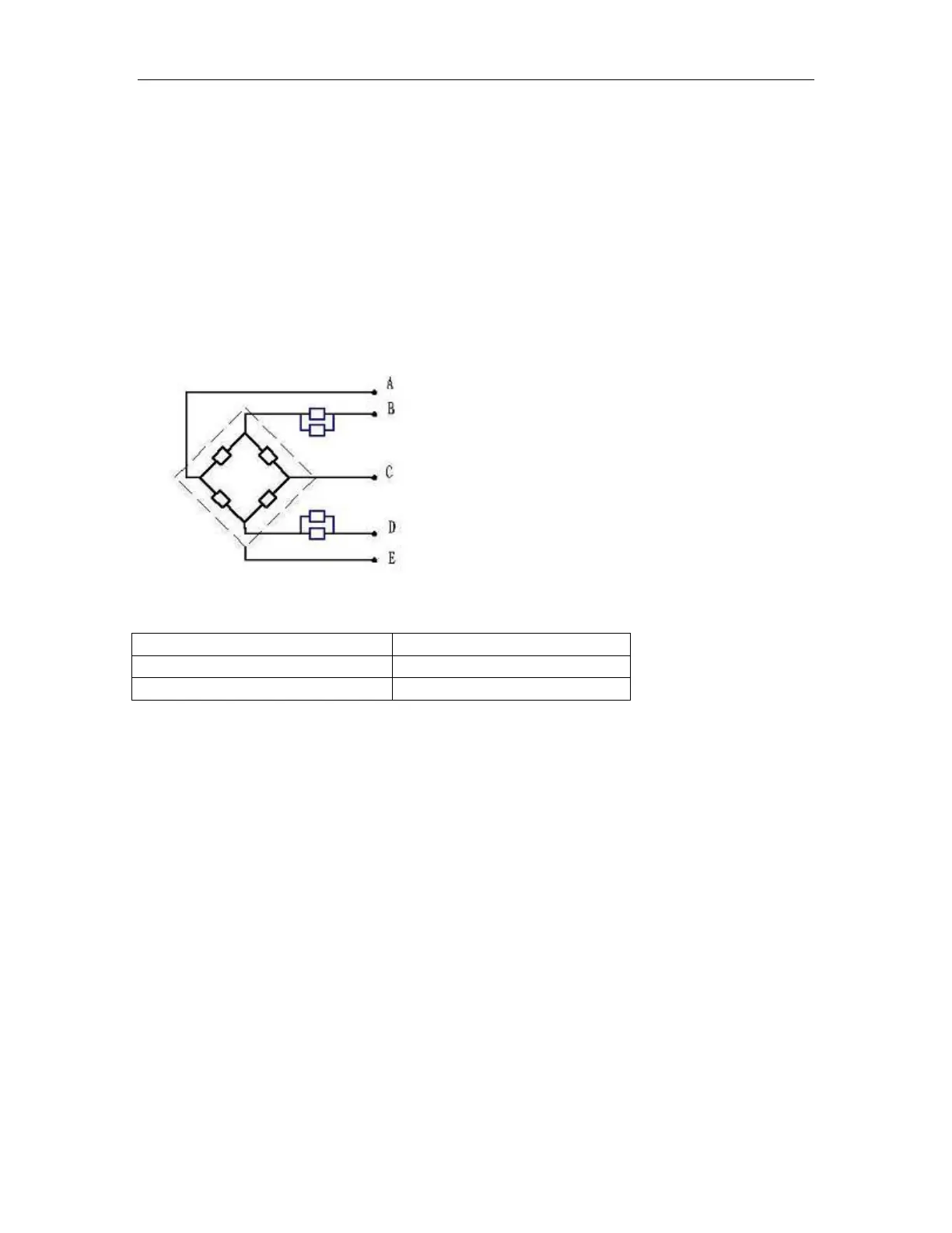
Load Cell Connections
Signal + Green
Supply + Red
Signal - Black
Supply - White
Shield
Red (+ Exc) to White ( –Exc)
Green (+Sig) to Black ( –Sig)
10.5. Check PCB Voltages
If the problem is in the PCB, use a multimeter to check the following voltages
10.5.1 AC Power
Check the AC power socket out put voltage.
Voltage must be a -20% and +10% of the normal AC voltage.
10.5.2 Adaptor Voltage
Check the adaptor output cable connecter voltage
Voltage must be minimum 9VDC and maximum 15VDC
 Loading...