14
Class A:
When the distance between the inverter and motor is longer than 100 meters, cable wire should be
carefully chosen to reduce the wiring resistance below 3% and the voltage drop (V) = √3 x Wire
resistance (Ω/km) x wire length (m) x current x 10
-3
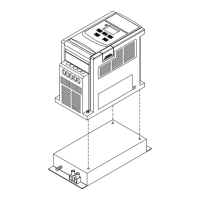
(B) Control circuitry wiring must be separated terminated and away from the primary power circuitry
and other high-voltage or large-current power lines to avoid noise interference.
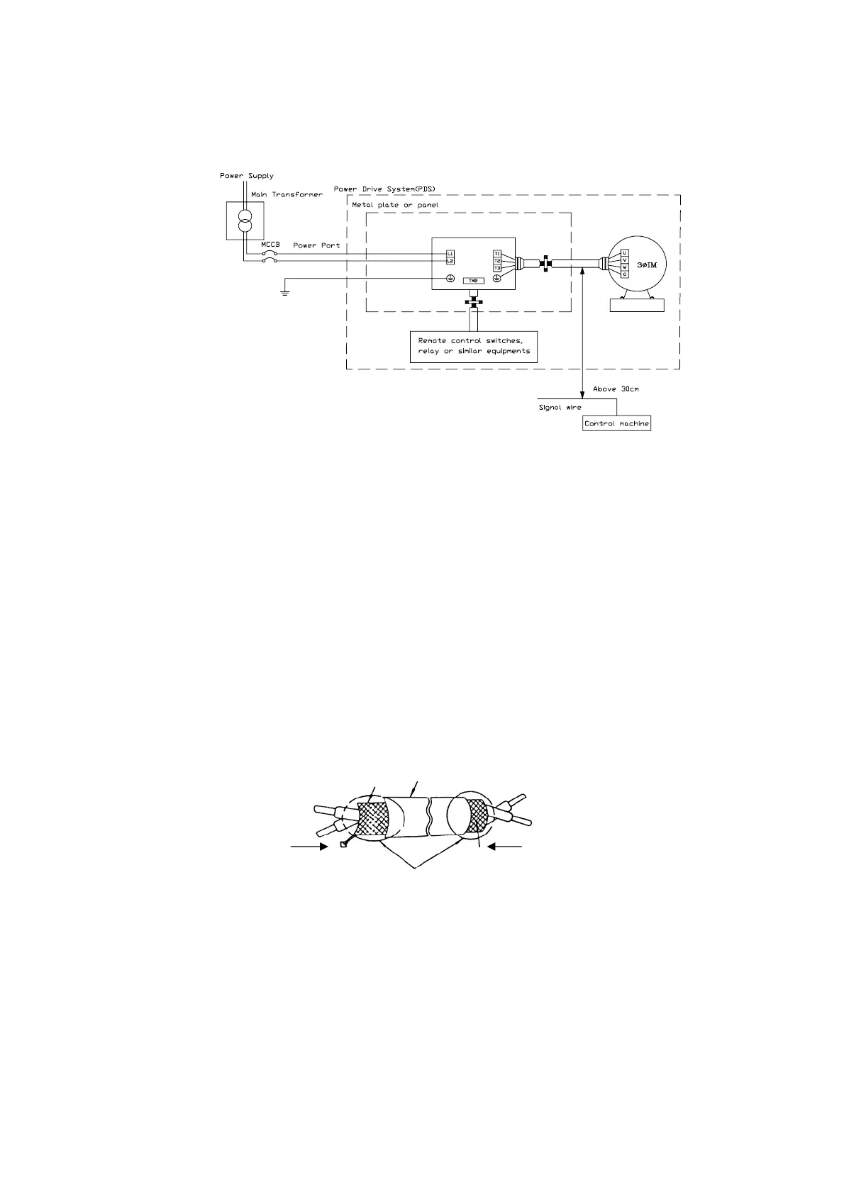
z To reduce the noise interference and avoid possible operational problems, shielded twisted pair
cable should be used to wire the control circuitry. Please refer to following diagram. Connect the
shielding wire onto the grounding terminal. Only connect one end of the shield.
Wiring distance must be under 50m.
(C) The grounding terminal of the inverter must be correctly grounded in compliance with 200V
class type three grounding.
z Grounding wire should be wired in accordance to electrical equipment (AWG) with the length
of the grounding wire as short as possible.
z The grounding wire of the inverter must not be grounded together with other large current
Shielding
Glove
To Inverter terminal
Connect to system grounding terminal
Wrapped with
insulating tape
To control machine
Do not connect the shielding
wire at this end
Drive
Connect Shield
 Loading...