24
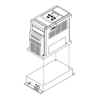
E2-2P2/2P5/201- - N4X(IP65)TYPE INSTALLATION :
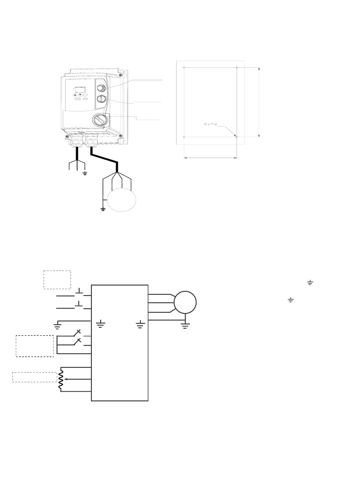
CIRCUIT DIAGRAM
NOTE:
(1). Input source : single-phase(L1,L2,
)ensuring
that it is connected to a 200/240V supply.
(2). Output Moter : three-phase(
,T1,T2,T3).
(3). POWER SWITCH , REV-0-FWD SWITCH AND
Potentiometer are only for E2-2P2~201- N4S TYPE.
Caution :
□Do not start or stop the inverter using the
main circuit power.
□FOR E2-2P2~201- -N4S TYPE :
Please always remain REV-0-FWD switch at 0
position. In order to keep inverter has no
running signal before power-on again after
power supply interrupted.Otherwise, injury may
result.
□FOR E2-2P2~201- -N4S TYPE :
Please always remain RE or FW switch at OFF
position. In order to keep inverter has no
running signal before power-on again after
power supply interrupted.Otherwise, injury may
result.
3
PHASE
IM
L1
L2
T1
T2
T3
FW
RE
12V
10V
VI
0V
POWER
SWITCH
REV-0-FWD
SWITCH
Potentiometer
AC
200~240
50/60HZ
Therminal : 5 kg-cm
(2) Remote control wire : 4 kg-cm
2. Motor cable : #16 AWG
(1).Power/Motor cable (plug-in)
3. Torque value of Screw :
1. Power supply cable : #14 AWG
mm
220-240V
50/60 Hz
Single Phases
L1 L2
3 Phases
IM
T1 T2 T3
SWITCH
POWER
Note :
RESET
RUN
STOP
Potentiometer
REV-0-FWD
ENT
DSP
FUN
DATA
SWITCH
mm
NOTE :
1. POWER SWITCH , REV-0-FWD SWITCH AND
Potentiometer are only for E2-2P2~201- N4S TYPE
2. Power supply cable : #14 AGE (2.0m )
3. Motor cable : #16 AGE (1.25m )
4. Torque value of Screw :
(1). Power/Motor cable (plug in) Therminal : 5kg-cm(4.34 in-lb)
(2). Remote control wire : 4kg-cm(3.47 in-lb)
(3). Outer Cover (M4) : 6kg-cm(5.20 in-lb)
123.40 mm
198.90 mm
㎡
㎡
 Loading...