18
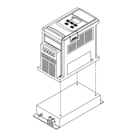
SW1 function description
SWITCH 1 External signal type
0~20mA analog signal (When F_11 is set to 1)
4~20mA analog signal (When F_11 is set to 2)
0~10 VDC analog signal (When F_11 is set to 1)
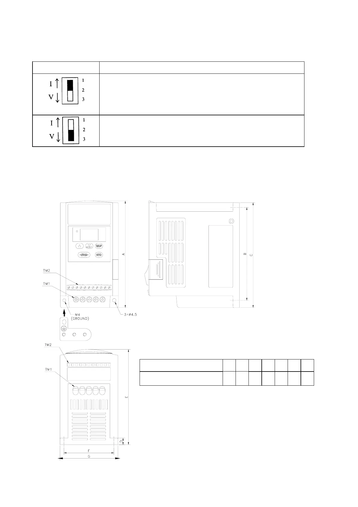
Dimensions & Location of terminal block
E2-1P2/1P5/101/2P2/2P5/201:
Unit: mm
DEMESIONS MODEL
A B C D E F G
E2-1P2/1P5/101/2P2/2P5/201 132 116 130 8.2 118 61 72
NOTE: For safety reason, we strongly recommend
users to remove the M4 grounding screw,
then screw the enclosed “metal frame
grounding terminal” on the same location to
make a grounding bar to ensure good earth
protection.
See NOTE
 Loading...