Air Chiller System (ACS) and Chiller Panel Getting Started Guide for the DMA 850 Page 17
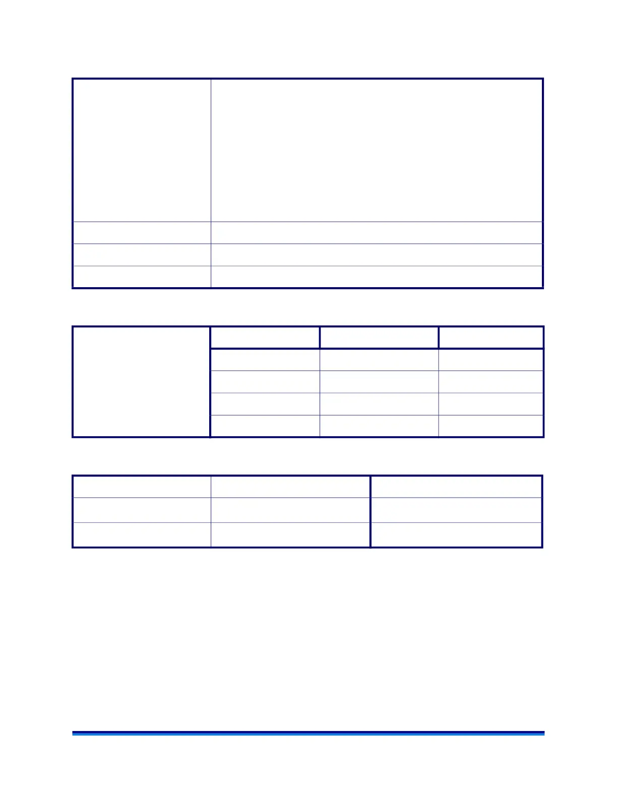
Table 4: Accessory Operating Environmental Conditions for ACS-2 and ACS-3
Table 5: Accessory Power Requirements for ACS-2 and ACS-3
Table 6: Accessory Performance Specifications
Ambient air 21°C–24°C = Ideal
NOTE: The ACS generates a significant quantity of heat when running. These
operating temperatures must be maintained during system operation.
Heat Generation:
ACS-2 50 Hz: 1450 W
ACS-2 60 Hz: 1450 W
ACS-3 50 Hz: 1750 W
ACS-3 60 Hz: 1600 W
*Refer to the serial number plate on the rear of the unit.
Operating altitude 2000 meters maximum
Relative humidity 5% to 80% RH from 15°C to 30°C
IP Rating The degree of protection for this instrument according to EN 60529 is IP20.
Electrical
*Refer to the serial number
plate on the rear of the unit
Part Number Voltage Frequency Current
405000.901 240V 60 Hz 9A
405000.902 220-230V 50 Hz 11A
405001.901 240V 60 Hz 8A
405001.902 220-230V 50 Hz 9.1A
Specification ACS-2 ACS-3
Lowest temperature
1
1. Lowest temperatures specified are achievable under ideal operating conditions. Actual temperature limits
will vary with ambient and compressed air temperatures and testing conditions.
-50°C
1
-100°C
1
Cooling rate:
see below
2
see below
2
2. Ramp Rate: The maximum sustainable ramp rate will depend on a number of factors particularly the start
and end temperature. To determine the maximum sustainable heating/cooling rate, perform the following
test and analysis:
a. Equilibrate to start temperature. Perform a time sweep or peak hold test with the temperature set (if
possible) to a few degrees in excess of the end temperature. Set the time much longer than you expect;
the test can be aborted when the temperature has reached a stable value.
b. Plot a graph of temperature vs. time (min) and take the derivative. Inspect the derivative curve over
your temperature range of interest. The maximum sustainable rate will be the lowest value on the de-
rivative curve.