-18-
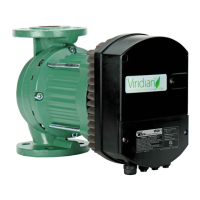
13 Controller Layout
VR 25H, VR 30M and VR30H controller
Terminal Designation Description
MODE
Mode selection rotary switch. Used to congure
mode of operation for the circuit. See section
14.3 “Module mode selection”
LED1 / LINK
Slowly blinking when module is powered.
Blinking fast when Modbus Error.
Permanently lid when Ethernet link established.
Ethernet 10BASE-T RJ-45 connector.
LED2 / ACT
Indicates Ethernet activity,
Modbus or BACnet activity.
B/D-
RS-485 negative data signal for
Modbus or BACnet.
A/D+
RS-485 positive data signal for
Modbus or BACnet
SET1 / RUN Control signal 1.
COM / 0V
RS-485 common and analog input
common (ground).
SET2 / MAX Control signal 2.
SET3 / FB Control signal 3.
NC
Normally closed relay contact.
Opens when relay is active.
C Relay common contact.
NO / NO
Normally open relay contact.
Closes when relay is active.
All models except VR25H, VR30M and VR30H
Analog Signals (SET1, SET2, SET3) • 12.5
Input Voltage Range -1 to 32 VDC When used as input.
Output Voltage Range 0 to 12 V When used as output. 5 mA max. Load allowed per output.
Input Resistance
~100 kW
0.5 mA load is added for most congurations.
--- --- Current sink to COM if congured as output.
Relay Specications • 12.6
Connection Type Screw-less terminals
Rating
- 250 VAC, 8A
Potential free changeover contact.
- 48VDC, Max Load up to 500VA
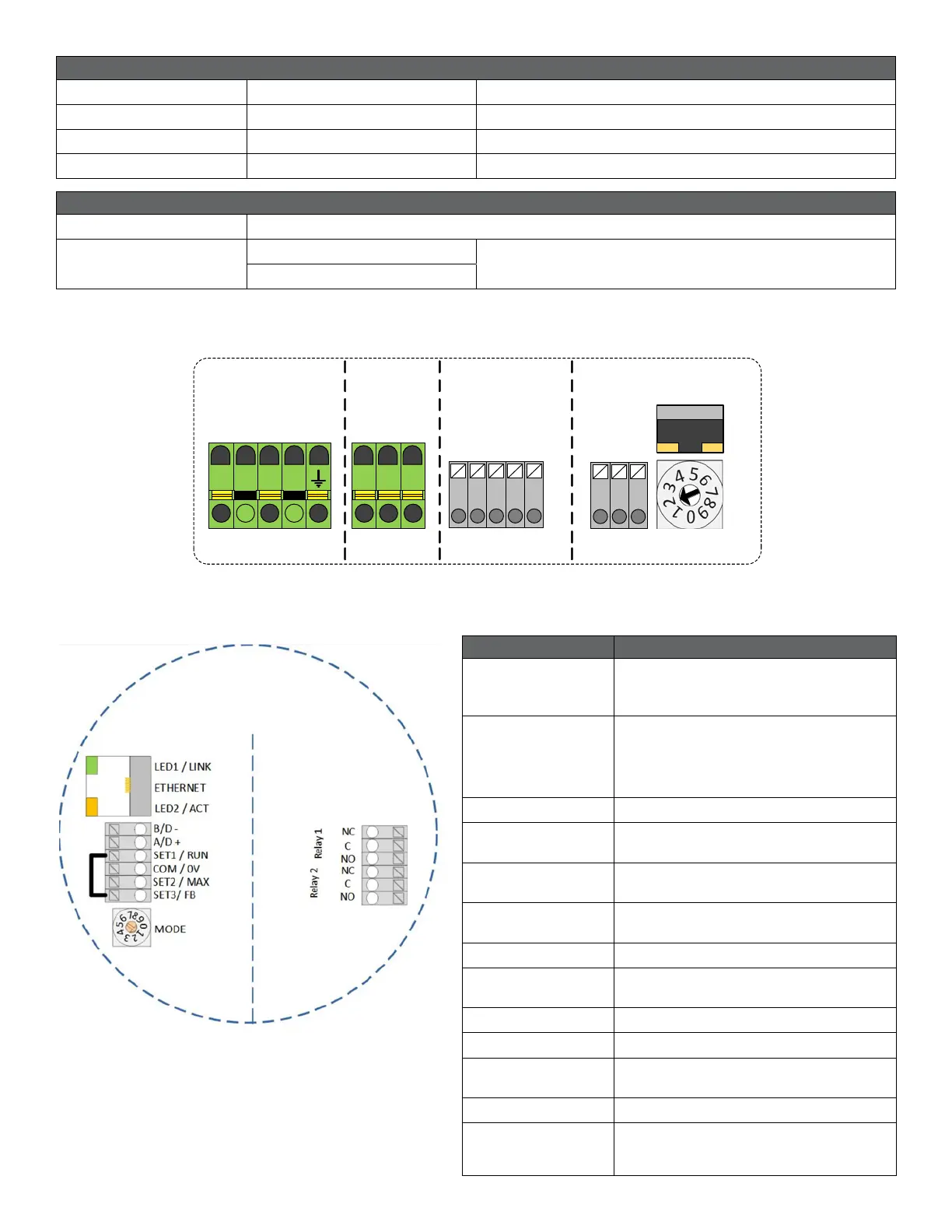
+24 V
SET3 / FB
SET2 / MAX
COM / ØV
SET1 / RUN
COM / ØV
B/D -
A/D +
NO
C
NC
GROUND
NEUTRAL
LINE
RS 485ANALOGRELAY
ETHERNET
LED1 LED2
L N