10
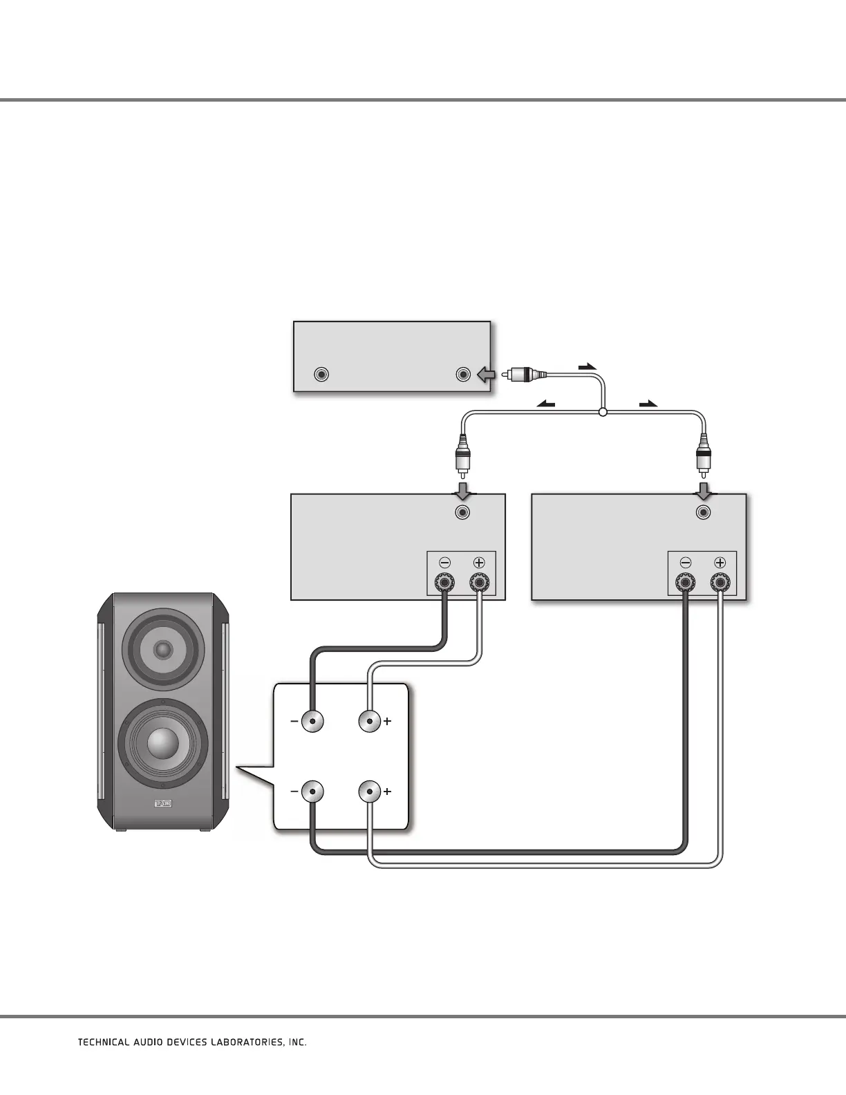
Horizontal Bi-Amping
With this connection method, independent stereo amplifiers are used respectively to drive the speaker’s LF circuit (for woofer) and HF
circuit (for CST).
As shown in Figure 5, each channel on one of the amplifiers is used to drive the speakers’ low-frequency range, while each channel of the
other amplifier is used to drive the high-frequency range of the two speakers.
In order to use this method, each of the amplifiers must possess the same gain value. If the two amplifiers have different gain values,
an imbalance will occur between the playback levels of the low-frequency and high-frequency ranges. Consult your dealer for further
information.
LF
HF
SPEAKERS OUTPUT
INPUT
SPEAKERS OUTPUT
INPUT
OUTPUTOUTPUT
Terminal Panel
Amplifier
(rear)
(Use for high frequencies)
Pre-Amplifier
(rear)
(one channel shown)
Amplifier
(rear)
(Use for low frequencies)
(one channel shown)
(one channel shown)
TAD Compact Evolution One
“Y” Adaptor
(Not supplied)
Figure 5. Connecting a TAD Compact Evolution One speaker in a horizontal bi-amplified system